Anastomosis System with Anvil Entry Hole Sealer

a technology of anastomosis and sealing device, which is applied in the field of surgical equipment and methods for performing anastomosis, can solve the problems of emboli detachment, time-consuming and labor-intensive suturing process, and high surgical skill, and achieves the effect of enhancing the sealing effect and minimizing the cross-sectional area of the anvil

Active Publication Date: 2008-01-31
AESCULAP AG
View PDF100 Cites 15 Cited by
  • Summary
  • Abstract
  • Description
  • Claims
  • Application Information

AI Technical Summary

Benefits of technology

[0007] In another aspect of an embodiment of the invention, the cap includes one or more attachment elements configured to engage and hold the graft vessel. As one example, the attachment elements may be spikes or other structures configured to penetrate one or more flaps at an end of the graft vessel. Alternately, at least one attachment element may be configured to hold the end of the graft vessel and / or at least one flap at an end of the graft vessel in another manner. For example, at least one attachment element may be a clip. One or more attachment elements may be fixed directly to or fixed relative to the staple holder. Motion of the one or more attachment elements on the cap relative to the one or more fixed attachment elements changes the spacing between the fixed and movable attachment elements, such that the spacing between the attachment elements can be adjusted to accommodate differently-sized flaps associated with a range of different widths of graft vessels. In this way, the tissue effector may be said to measure the width of the graft vessel, such that the number of tools and / or steps required to prepare for anastomosis may be reduced. For example, the transfer clamp assembly may be omitted where the tissue effector measures the width of the graft vessel.
[0008] In another aspect of an embodiment of the invention, the connectors are staples, such as wire staples. Wire staples may be advantageous due to their ease of production and low cost. However, the connectors may be other types of staples, or may be configured in any other manner that allows them to connect the graft vessel to the target vessel. The connectors may be all of the same type, or different types of connectors may be mixed within the same tissue effector.
[0011] In another aspect of an embodiment of the invention, a cutter assembly is movable through at least part of a channel defined in the anvil, and the cutter assembly includes a pusher, a projection positioned distal to the pusher, and a member connected to the projection. The projection may include a sharp edge and a blunt edge. As one example of the operation of the cutter assembly, the projection is initially inside the channel of the anvil in a stowed position. In this way, the cross-sectional area of the anvil is minimized, as is the size of the anvil entry hole in the target vessel. Proximal motion of the member causes the proximal end of the projection to contact the distal end of the pusher, both of which are angled or otherwise shaped such that this contact urges an end of the projection upward out of the channel to an active position to penetrate the wall of the target vessel. Motion of the pusher urges the projection through tissue, creating an opening in the wall of the target vessel. As the anvil is removed from the target vessel, the blunt edge of the projection encounters the proximal end of the opening in the target vessel. This contact causes the projection to move into the channel to a withdrawal position, such that the anvil can exit the anvil entry hole without the projection substantially enlarging it.
[0012] In another aspect of an embodiment of the invention, another embodiment of the cutter assembly includes a pusher and a projection having a lobe defined thereon, where the lobe is configured to be received by a slot in the anvil. When the projection is in the stowed position, the lobe is positioned within the slot in the anvil, and is substantially inside the channel in the anvil. As the pusher advances distally, it engages the projection and urges the lobe out of the slot, thereby causing at least a portion of the projection to move out of the channel in the anvil to an active position to penetrate the wall of the target vessel. Further distal motion of the pusher moves the projection through tissue, creating an opening in the wall of the target vessel. As the anvil is removed from the target vessel, the blunt edge of the projection encounters the proximal end of the opening in the target vessel. This contact causes the projection to move into the channel to a withdrawal position, such that the anvil can exit the anvil entry hole without the projection substantially enlarging it.
[0013] In another aspect of an embodiment of the invention, the tissue effector is configured to deploy connectors on opposite lateral sides of the anastomosis closer together at the heel and / or toe than at other longitudinal positions along the anastomosis. To do so, the most-proximal and / or most-distal connector bays on each arm may be offset relative to the remaining connector bays. By placing connectors closer together at the heel and / or toe of the anastomosis, sealing of the anastomosis may be enhanced.

Problems solved by technology

The suturing process is a time consuming and difficult procedure requiring a high level of surgical skill.
This suturing requires a high degree of precision and is quite time consuming.
The use of a side clamp or similar device can cause emboli to detach from the wall of the aorta and enter the bloodstream, which is undesirable.

Method used


Image

  • Anastomosis System with Anvil Entry Hole Sealer
  • Anastomosis System with Anvil Entry Hole Sealer
  • Anastomosis System with Anvil Entry Hole Sealer

Examples


Embodiment Construction

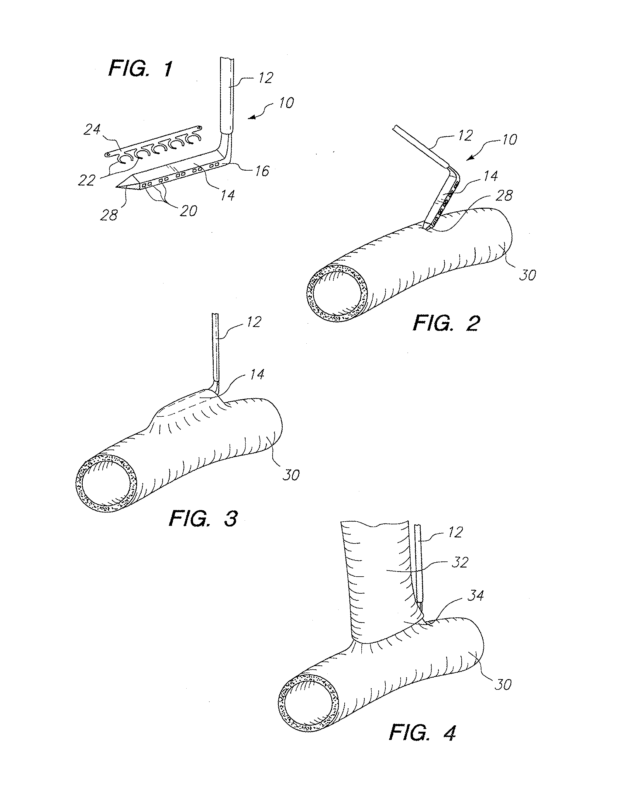
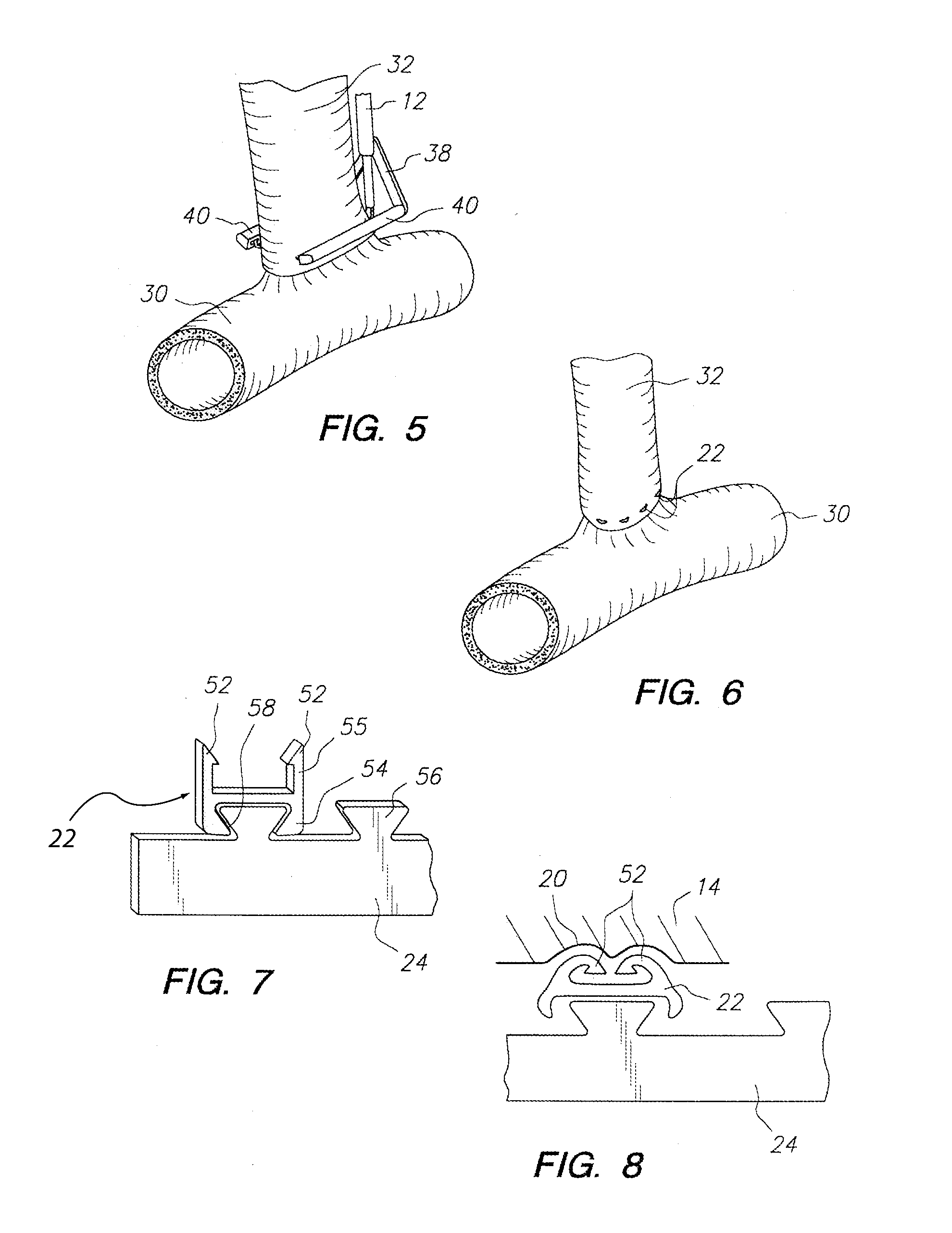
[0148] As shown in FIG. 1, one embodiment of an anvil 10 includes a handle 12 and an anvil arm 14 extending from the handle 12. The anvil arm 14 may be oriented substantially perpendicular to the handle 12, or oriented at a different angle. The anvil arm 14 may be provided with one or more staple bending features 16 on opposite sides of the anvil arm 14. In the anvil 10 shown in FIG. 1, the staple bending features 16 each include a plurality of recesses 20 which receive the ends of staples 22 and cause the staple ends to bend over. At least one of the staple bending features 16 may be configured differently or omitted, if desired. The staples 22 may be connected to a staple holding strip 24. The staples 22 are U-shaped and are arranged in a spaced apart parallel configuration such that the staples 22 all lie in a single plane. Alternately, the staples 22 may be shaped differently, and / or lie in one or more different planes. An exemplary anvil arm 14 has a height and a width of about...


PUM


Abstract

A system for connecting the end of a graft vessel to the side of a target vessel may include an anvil configured to enter the target vessel through an anvil entry hole in the wall of the target vessel; a holder movable relative to the anvil, where that holder may deploy at least one connector through the graft vessel and into the target vessel at a location spaced apart from the anvil entry hole; and at least one sealer that may be detachably connected to the anvil and / or said holder; where at least one sealer may be configured to substantially close the anvil entry hole in the target vessel. A method for performing anastomosis between a graft vessel and a target vessel may include inserting an anvil through the wall of the target vessel into the lumen of the target vessel from outside of the target vessel through an anvil entry hole; connecting an end of the graft vessel to the side of the target vessel with a plurality of connectors at a location spaced apart from the anvil entry hole; creating an opening in the side of the target vessel, where the opening is located within a perimeter defined by the connectors and spaced apart from the anvil entry hole; withdrawing the anvil through the anvil entry hole; and substantially sealing the anvil entry hole.

Description

[0001] This application is a divisional of U.S. patent application Ser. No. 10 / 720,618, which is hereby incorporated by reference in its entirety.FIELD OF THE INVENTION [0002] The invention relates to a surgical apparatus and method for performing anastomosis.BACKGROUND [0003] Anastomosis is a procedure by which two hollow tissue structures are joined together. More particularly, vascular anastomosis is a procedure by which two blood vessels within a patient are surgically joined together. Vascular anastomosis is performed during treatment of a variety of conditions including coronary artery disease, diseases of the great and peripheral vessels, organ transplantation, and trauma. In coronary artery disease (CAD) an occlusion or stenosis in a coronary artery interferes with blood flow to the heart muscle. Treatment of CAD involves the grafting of a vessel in the form of a prosthesis or harvested artery or vein to reroute blood flow around the occlusion and restore adequate blood flow...

Claims


Application Information

Patent Timeline
Patent Type & Authority Applications(United States)
IPC IPC(8): A61B17/11
CPCA61B17/00491A61B2019/481A61B17/0206A61B17/06166A61B17/064A61B17/0644A61B17/0686A61B17/072A61B17/07207A61B17/08A61B17/10A61B17/115A61B17/1152A61B17/122A61B17/32A61B19/26A61B2017/00654A61B2017/00893A61B2017/0641A61B2017/0688A61B2017/07214A61B2017/1103A61B2017/1107A61B2017/1135A61B2017/1157A61B2017/320052A61B17/0057A61B90/50A61B2090/08021
Inventor NIELSEN, JAMES T.WHITE, NATHAN H.BENDER, THEODORE M.MANOUX, PHILIPE R.BOMBARD, DAVID L.DONOHOE, BRENDAN M.KNODEL, BRYAN D.
Owner AESCULAP AG
Why Eureka
Try Eureka