
Electrode device for active medical implant

a technology of active medical implants and electrode devices, which is applied in the direction of measurement devices, impedence networks, instruments, etc., can solve the problems of considerable heating and serious problems of the compatibility of such electrode devices in the case of implantable electromedical devices having high-frequency magnetic fields of the type used in imaging diagnostic methods in particular, so-called mri (magnetic resonance imaging) methods

Inactive Publication Date: 2013-09-03
BIOTRONIK SE & CO KG
View PDF6 Cites 0 Cited by
  • Summary
  • Abstract
  • Description
  • Claims
  • Application Information

AI Technical Summary

Benefits of technology

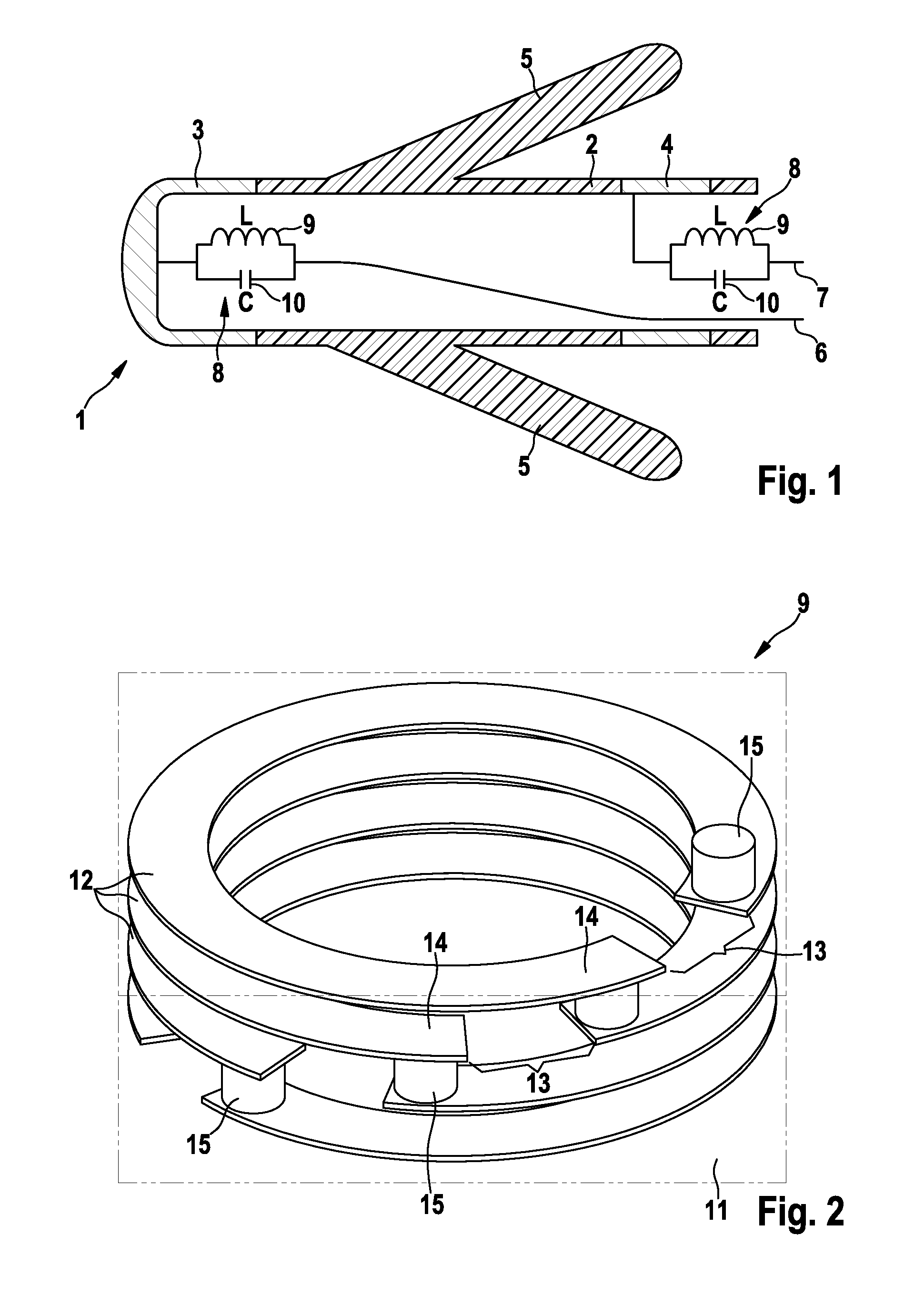
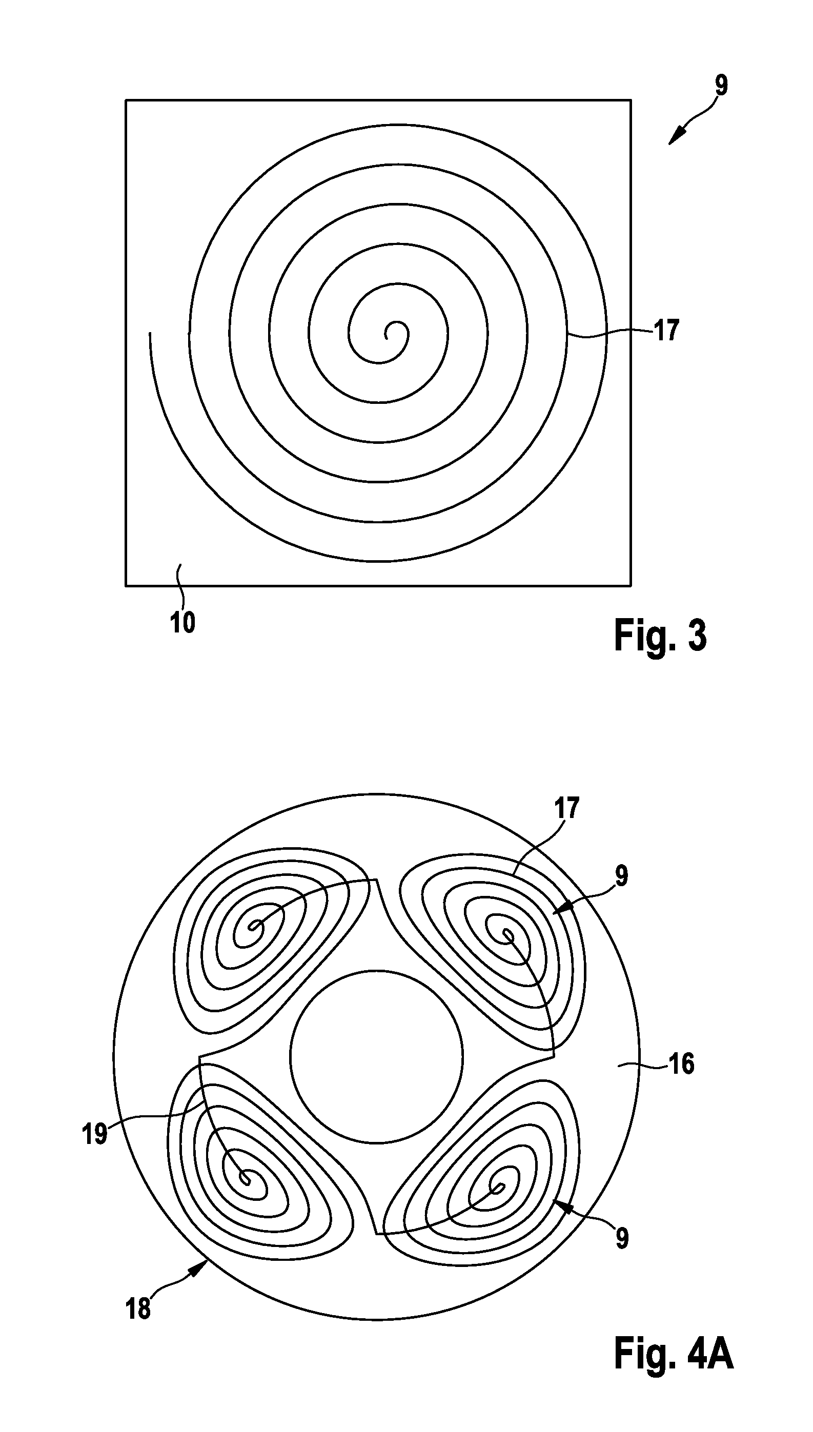
This technology combines the benefits of two existing technologies, high temperature cofired ceramics and thick film, to create a low-cost alternative to printed circuit boards. The use of LTCC components allows for the high integration of small-sized high-frequency filters, which stiffen the electrode device less than traditional methods. The coil design allows for a compact size and flexibility, making it ideal for small item counts in medical engineering.

Problems solved by technology

The compatibility of such electrode devices in the case of implantable electromedical devices having high-frequency magnetic fields of the type used in imaging diagnostic methods in particular which are based on magnetic resonance—so-called MRI (magnetic resonance imaging) methods—is a serious problem.
This can result in considerable heating e.g. of the tip contact of a cardiac electrode with corresponding impairment and even damage of the cardiac tissue in contact therewith or that surrounds it.
The filters disclosed in that known patent are designed—in practical application by the patent owner—as relatively voluminous components that stiffen the electrode device along a certain length and impart unfavorable mechanical properties to the electrode equipped therewith.
Furthermore, the filter is accommodated in a closed housing that does not provide passage for the guide wires that are typically used when implanting an electrode.
To this extent, the potential uses of this known electrode with filter devices is limited.
The filter devices according to the prior art typically result in excessive stiffening of the electrode device along a certain length.
They are relatively complex and not very compact.

Method used


Image

  • Electrode device for active medical implant
  • Electrode device for active medical implant
  • Electrode device for active medical implant

Examples


Embodiment Construction

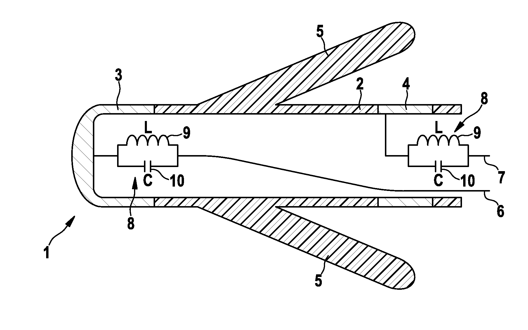
[0027]FIG. 1 shows the region of distal end 1 of an electrode device that comprises an elongated electrode body 2 composed of a flexible, insulating tube.

[0028]A tip contact pole 3, which is usually referred to as a tip electrode, is fastened to the tip of electrode body 2; when used in the electrode device, tip contact pole 3 is brought into contact with cardiac tissue, for example.

[0029]A ring contact pole 4 is fastened in electrode body 2, before tip contact pole 3 in the proximal direction, and at a distance therefrom; ring contact pole 4 is likewise used to output electrocardiological stimulating currents or to measure electrocardiological signals. A plurality of silicone anchors 5 for fastening the electrode device to a suitable point in the cardiac tissue project obliquely outward from electrode body 2 in the proximal direction between tip and ring contact poles 3, 4, respectively.

[0030]The electrical connection between an electromedical implant, such as a cardiac pacemaker, ...


PUM


Abstract

An electrode device for active medical implants that includes an elongated electrode body having a proximal end and a distal end, a tip contact pole on the distal end and / or a ring contact pole before the distal end, electrical supply leads to the tip and ring contact poles, and a high-frequency filter in at least one of the supply leads, which is composed of one or more electronic components (9) and is assigned to the tip and / or ring contact pole, wherein the electronic component(s) (9) are each designed as a miniature component using LTCC technology.

Description

[0001]This application takes priority from German Patent Application DE 10 2010 000 372.7, filed 11 Feb. 2010, the specification of which is hereby incorporated herein by reference.BACKGROUND OF THE INVENTION[0002]1. Field of the Invention[0003]Embodiments of the invention relate to an electrode device for active medical implants, which comprises an elongated electrode body having a proximal end and a distal end, a tip contact pole on the distal end and / or a ring contact pole before the distal end, electrical supply leads to the tip contact pole and the ring contact pole, and a high-frequency filter in at least one of the supply leads, which is composed of one or more electronic components and is assigned to the tip and / or ring contact pole.[0004]2. Description of the Related Art[0005]Regarding the background of the invention, it should be pointed out that the subject matter of one or more embodiments of the invention is relevant primarily in conjunction with cardiac pacemakers, imp...

Claims


Application Information

Patent Timeline
Patent Type & Authority Patents(United States)
IPC IPC(8): A61N1/00
CPCA61N1/05H03H1/0007H03H7/0115H03H7/1766A61N2001/086G01R33/288H03H2001/0085A61N1/086
Inventor WEISS, INGOFRIEDRICH, MICHAELKNORR, STEFANFISCHER, RENESCHURR, MARC STEFFEN
Owner BIOTRONIK SE & CO KG
Learn More