Method and apparatus for securing a conduit to a structure

a technology of conduits and structures, applied in the direction of liquid bottling, vehicles/pulleys, ropes and cables, etc., can solve the problems of uncontrollable manner, risky current process, environmental damage, etc., and achieve the effect of less operator skills, less risk to operating personnel, and convenient us

Inactive Publication Date: 2013-09-10
DEEP TEK UNDERWATER IP
View PDF14 Cites 7 Cited by
  • Summary
  • Abstract
  • Description
  • Claims
  • Application Information

AI Technical Summary

Benefits of technology

[0028]Embodiments of the invention typically allow securing of the conduit in place from only one side of the tank. The complete operation of attaching a pipe may be undertaken quickly and in one step without withdrawing taps or drills to fasten bolts in the holes as that may allow fluid or gas to escape. This method may be used more easily in hazardous areas and ultra deep water with less risk to operating personnel.
[0029]Embodiments of the invention typically require fewer operator skills because the driving mechanisms can be set up on the surface prior to the system being attached to the structure. Embodiments can be quickly clamped (temporarily or permanently) to the structure (e.g. using magnets) and the pipe can be attached from one side of the structure within minutes. Embodiments of the equipment can be easily transported and can be operated on different vessels ranging from small fishing boats to large ships.

Problems solved by technology

Many submerged structures such as sunken ships etc contain large amounts of oil or other fluids that would be environmentally damaging to release into the surrounding environment in an uncontrolled manner.
The current process can be risky if the liquid or gas in the tank is under pressure, or is flammable or toxic, and it is always time consuming and difficult, and therefore expensive in terms of diver time and level of skill needed.
The time and expense is compounded by the fact that oil frequently spills from the tank or machinery spaces of most wrecks and some of it remains trapped within other parts of the ships structure.

Method used


Image

  • Method and apparatus for securing a conduit to a structure
  • Method and apparatus for securing a conduit to a structure
  • Method and apparatus for securing a conduit to a structure

Examples


first embodiment

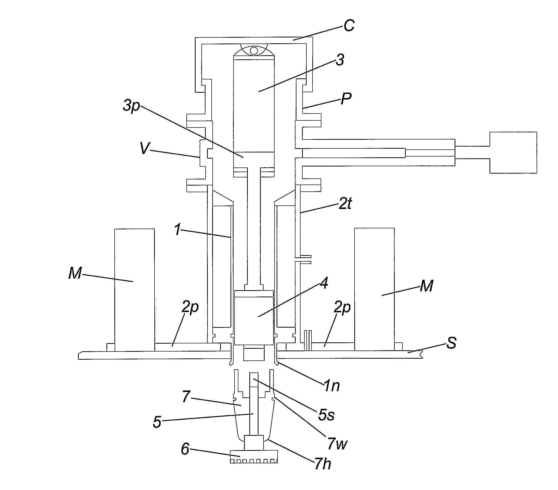
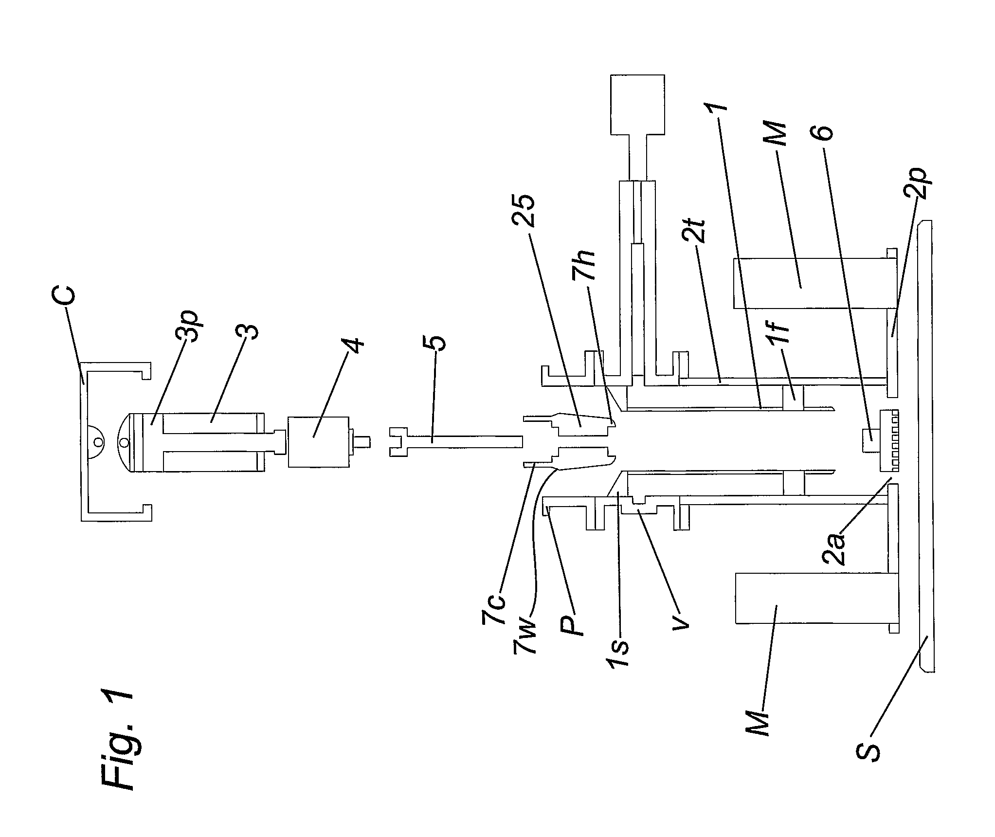
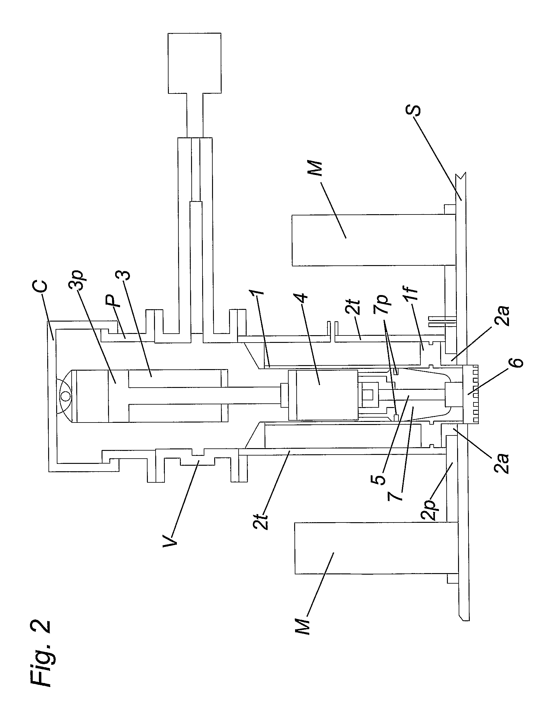
[0076]Referring now to the drawings, FIG. 1 shows a first embodiment for attaching a conduit to a structure S. In the FIG. 1 exploded view, the conduit comprises a cylindrical pipe 1 having an external flange 1f that is spaced from one distal end. As best shown in FIGS. 5 and 6, the apparatus for attaching the pipe 1 comprises a guide plate 2p that is flat and rectangular, and a guide tube 2t with a hollow bore that extends perpendicularly from the upper face of the guide plate 2p. The guide tube 2t is welded to the guide plate 2p, and is co-axial with and surrounds a central aperture 2a in the guide plate 2p which is slightly narrower than the bore of the guide tube 2t, so that a radially extending lip is formed between the aperture 2a and the lower face of the tube 2t. The bore of the guide tube 2t and the aperture 2a are coaxial.

[0077]The upper end of the guide tube 2t is flanged to accept a valve housing V carrying a valve that is adapted to close the bore of the valve housing V...

seventh embodiment

[0117]Referring now to FIGS. 34-48, a seventh embodiment is particularly useful for attaching a conduit to a structure having two skins, an outer skin, such as an outer wall of a ship's hull S1, and an inner skin, such as an oil tank S2, which is spaced from the outer hull S1, and which contains the fluid (e.g. oil) to be recovered. Normally the space between the outer and inner hulls in such ships is around 1m, but it is not a constant factor. In the FIG. 34 view, the conduit comprises a cylindrical pipe 71 having an external flange 71f that is spaced from one distal end, and a guide plate 72 similar to earlier embodiments. The guide plate 72 having a guide tube 72t has annular seals on its inner surfaces at 72s, and is adapted to attach temporarily to the hull S1 via magnets or other connections as previously described.

[0118]The upper end of the guide plate 72 is open to accept the pipe 71 and connect it to the structure S1 and S2.

[0119]The pipe 71 is a tight fit within the bore o...


PUM

PropertyMeasurementUnit
diameteraaaaaaaaaa
dimensionaaaaaaaaaa
inner circumferenceaaaaaaaaaa

Abstract

A method and apparatus for securing a conduit to relatively inaccessible structures, for example, oil tanks on submerged ships. The method involves providing a conduit with a neck, temporarily securing the conduit to the surface, for example by means of magnets, etc, drilling a hole through the structure and passing the neck of the conduit through the hole in the structure, and passing an expander device through the neck of the conduit through the hole in the structure to widen a portion of the internal passage of the conduit in the region of the neck.

Description

[0001]This Application is the U.S. National Phase Application of PCT International Application No PCT / GB2008 / 000273 filed Jan. 28, 2009[0002]This invention relates to a method and apparatus for securing a conduit to a structure. The structure typically contains fluids to be removed through the conduit. Some embodiments may be useful for structures into which fluids are to be injected through the conduit. Embodiments of the invention are particularly useful for attaching conduits such as pipes to structures that are relatively inaccessible, for example, tanks and other structures that are submerged in water and only allow access to one face of the tank. Some embodiments are useful for attaching pipes for the removal of oil and other environmentally damaging fluids from submerged ships.DESCRIPTION OF THE RELATED ART[0003]Many submerged structures such as sunken ships etc contain large amounts of oil or other fluids that would be environmentally damaging to release into the surrounding...

Claims


Application Information

Patent Timeline
Patent Type & Authority Patents(United States)
IPC IPC(8): B21D39/00B23P11/00
CPCB63C7/006F16L41/04F16L41/082Y10T29/4994Y10T403/4924Y10T29/49833Y10T29/4992Y10T29/53722
Inventor CRAWFORD, ALEXANDER CHARLES
Owner DEEP TEK UNDERWATER IP
Why Eureka
Try Eureka