
Flow splitter

a technology of flow splitter and flow valve, which is applied in the direction of valve operating means/releasing devices, water supply installation, transportation and packaging, etc., can solve the problems of increasing the system pressure drop, device flow range is limited, and devices need to be recalibrated

Active Publication Date: 2013-09-10
PARKER INTANGIBLES LLC
View PDF12 Cites 5 Cited by
  • Summary
  • Abstract
  • Description
  • Claims
  • Application Information

AI Technical Summary

Benefits of technology

The present invention is a flow splitter that uses two diaphragm valves to control the flow through two outlets. The valves are arranged in opposite directions and are connected to move together using a coupler. This design allows for precise control of the flow through each outlet using a single actuator. It also eliminates the need for additional sensors and reduces the size of the motor required to operate the valves. The coupling of the valves helps to balance the pressure load and makes the valves easier to operate.

Problems solved by technology

The output signal of these sensors is a function of the flow rate through each sensor; therefore these devices have a limited flow range.
In addition, thermal and pressure sensors drift over time, so that these devices need to be re-calibrated.
This increases the system pressure drop and slows the response of the gas delivery system.
This can take up to ten seconds, which represents a significant delay in semiconductor processing.

Method used


Image

  • Flow splitter
  • Flow splitter
  • Flow splitter

Examples


Embodiment Construction

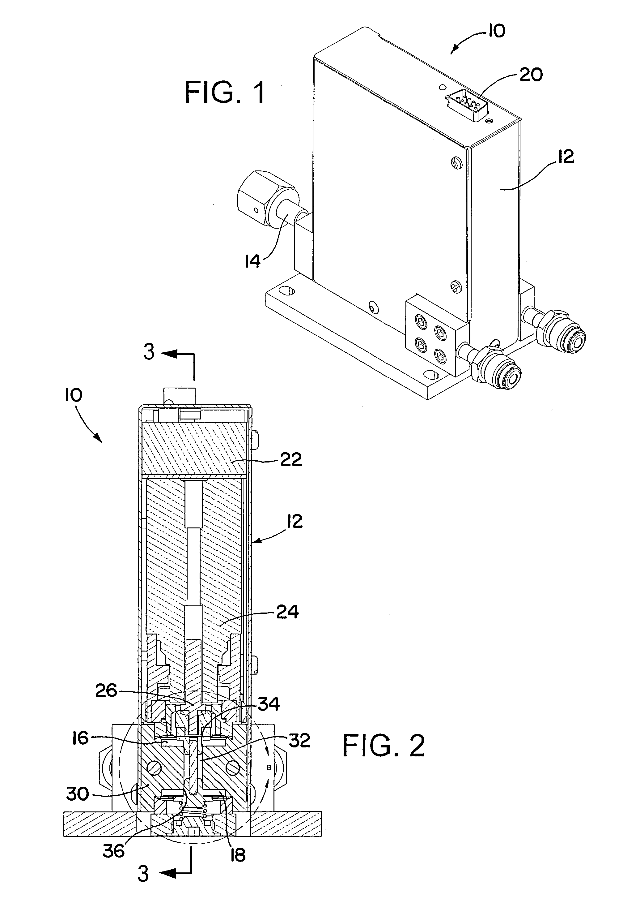
[0030]Referring now to the drawings in detail and initially to FIG. 1, an exemplary flow splitter according to the invention is indicated generally by reference numeral 10. The flow splitter 10 can be seen to include a housing 12 having an inlet 14 and a pair of outlets 16 and 18. The housing further has an electrical connector 20 for conveniently effecting connection of electronics contained within the housing to external components, as in a conventional manner. The inlet and outlets may each have associated therewith a suitable fitting as shown.

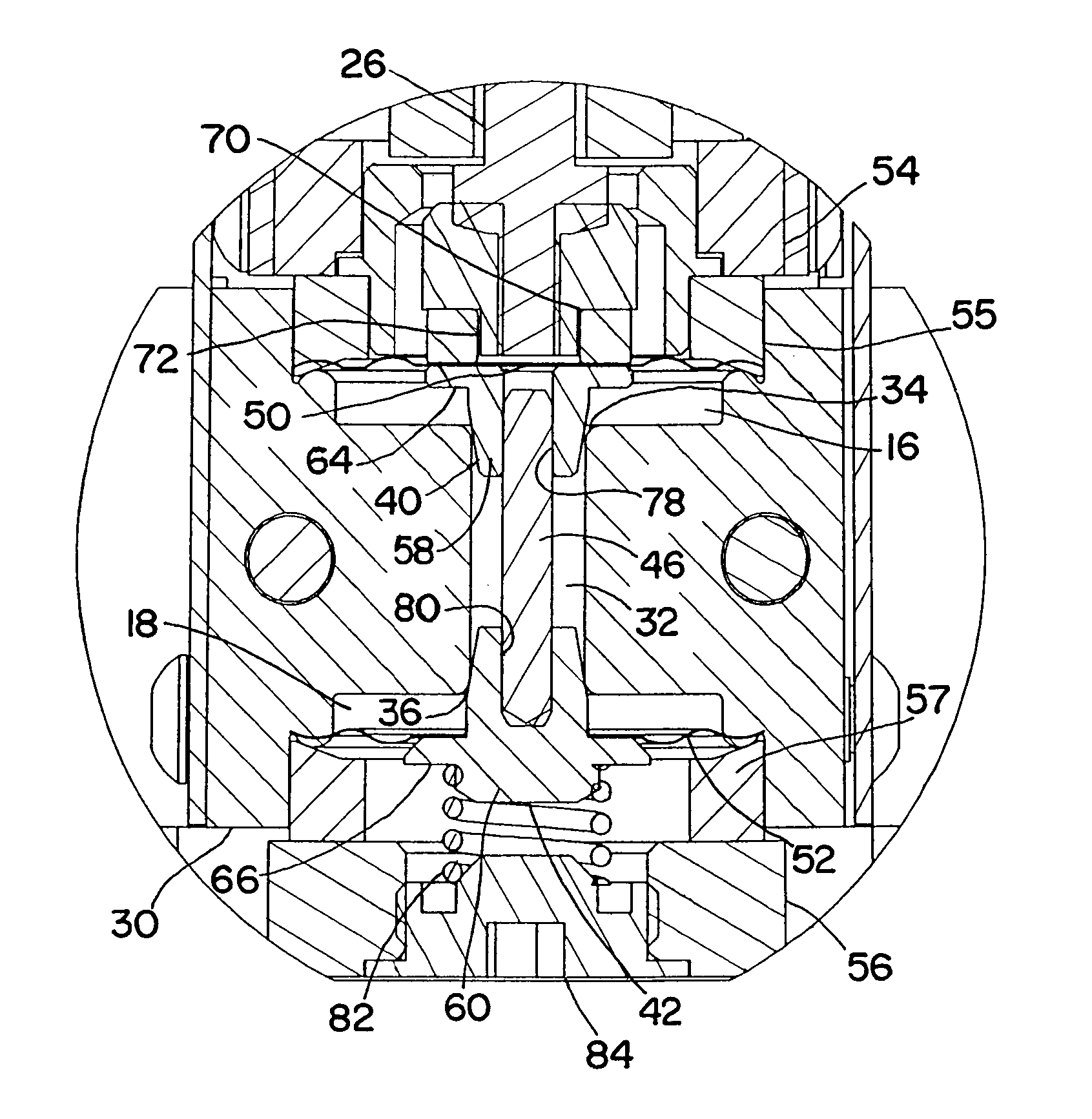
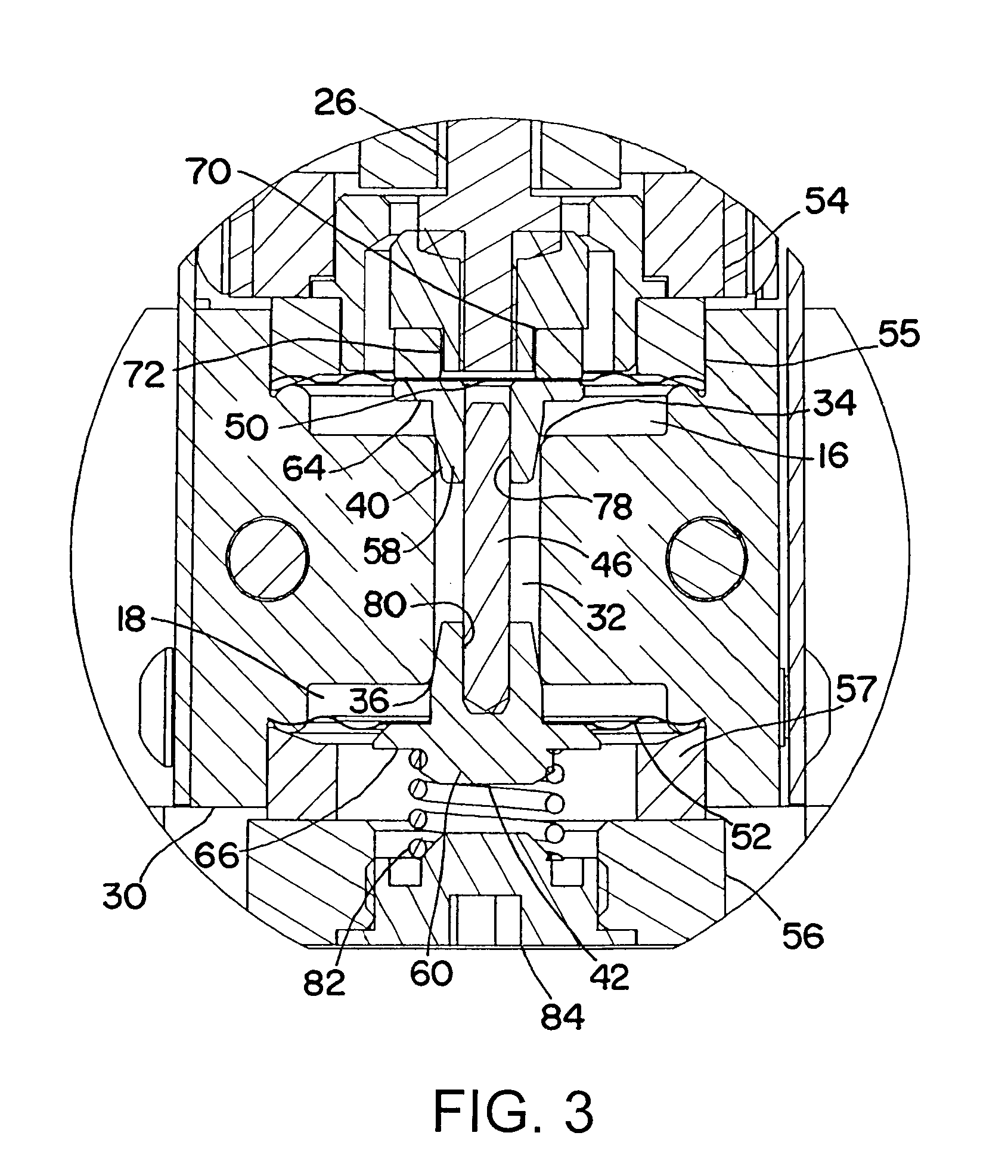
[0031]Referring now to FIG. 2, the upper portion of the housing 10 may contain the valve splitter electronics 22, such as a motor controller, for controlling a motor 24 having an output shaft or other member 26. The lower end of the housing contains or forms a valve body 30 that has a common passage 32 connected to the inlet 14 and extending between oppositely facing valve seats 34 and 36 disposed between the common passage and the outlets ...


PUM


Abstract

A flow splitter (10) that is uniquely characterized by the use of two diaphragm valves in a single valve body that are arranged in opposition to one another. The diaphragm valves are coupled together for common movement by a coupler, such that the flow rate through respective outlets is a function of the position of either diaphragm valve. That is, the position of one valve is a function of the position of the other valve, and vice versa. With this construction a single actuator can control the ratio of total flow that will be delivered to each of two outlet ports. Moreover, such construction eliminates the need for thermal or pressure sensors and thus the drawbacks associated therewith.

Description

[0001]This application is a national phase of International Application No. PCT / US2008 / 061729 filed Apr. 28, 2008 and published in the English language.RELATED APPLICATIONS[0002]This application claims the benefit of U.S. Provisional Application No. 60 / 950,883 filed Jul. 20, 2007, which is hereby incorporated herein by reference.FIELD OF THE INVENTION[0003]The present invention is directed to fluid processing systems, and more particularly to a system and method for dividing a single mass flow into a desired ratio of two or more flows. The invention has particular application to semiconductor processing equipment wherein precisely metered quantities of process gases are delivered to semiconductor process chambers.BACKGROUND OF THE INVENTION[0004]Fluid processing systems are used in the semiconductor and pharmaceutical industries (as well as in other industries) to provide a precise quantity of fluid or fluids to a processing chamber. For example, in the semiconductor industry, fluid...

Claims


Application Information

Patent Timeline
Patent Type & Authority Patents(United States)
IPC IPC(8): F16K11/048
CPCG05D11/003Y10T137/86895Y10T137/0318Y10T137/87788Y10T137/87764
Inventor MORGAN, DANIEL P.
Owner PARKER INTANGIBLES LLC
Learn More