
Passive boundary layer control elements

a control element and boundary layer technology, applied in the field of vortex generators, can solve the problems of reducing their strength, and reducing the efficacy of controlling the boundary layer, so as to achieve low fluctuation levels, dramatic reduction of interaction fluctuations, and reduction of fluctuation levels

Inactive Publication Date: 2013-09-10
RGT UNIV OF MICHIGAN
View PDF9 Cites 16 Cited by
  • Summary
  • Abstract
  • Description
  • Claims
  • Application Information

AI Technical Summary

Benefits of technology

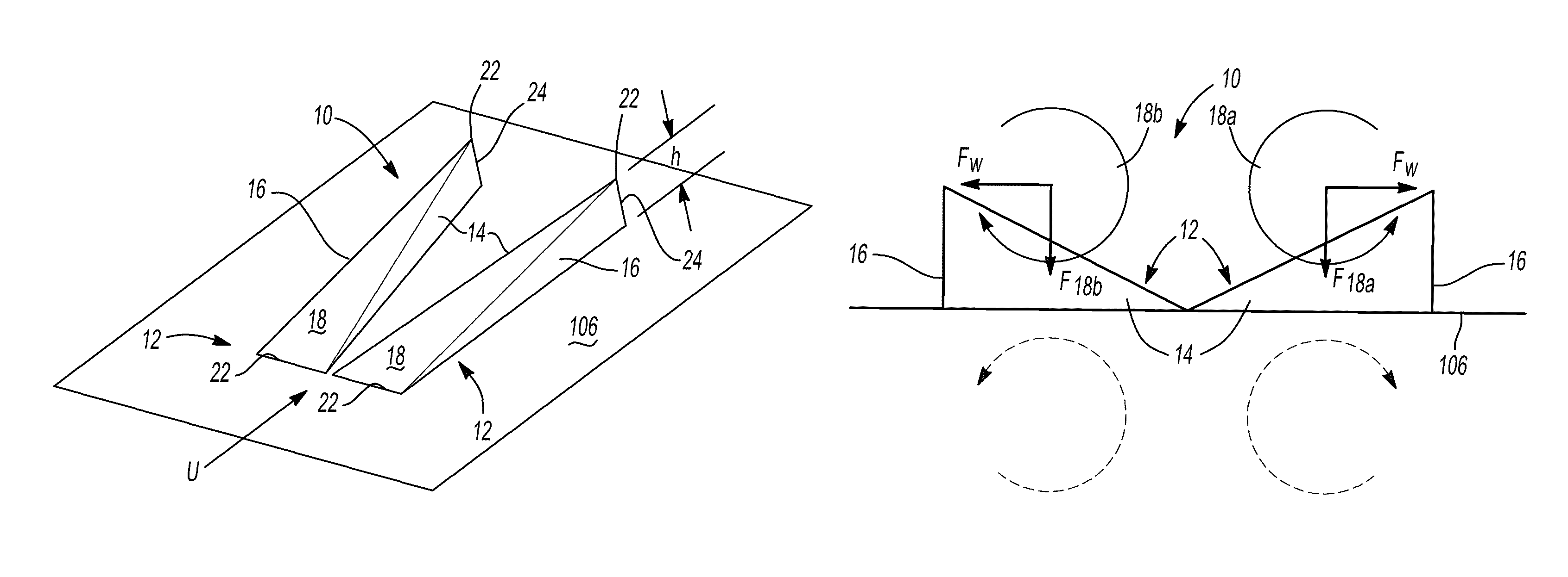
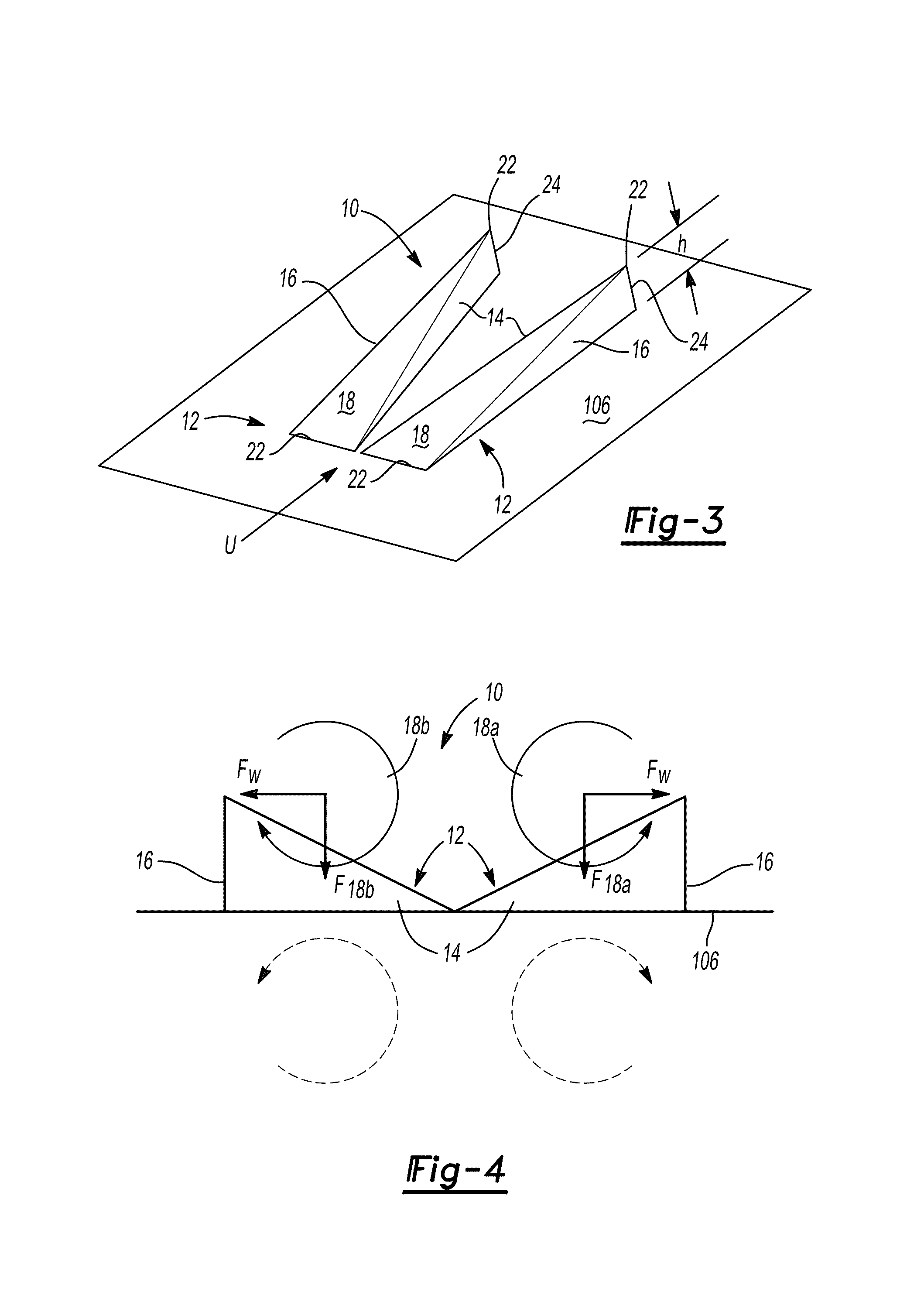
The patent describes a new design of micro ramps that can improve boundary layer control in flow applications. These micro ramps can create vortices that align with the direction of the stream, which helps to pull high energy fluid from the free stream deep into the boundary layer to avoid separation and other unwanted effects. This design can produce a more energetic boundary layer with less thickening and separation caused by an adverse pressure gradient. The new design has several key benefits, including maximum vorticity, total circulation, spanwise separation, and the wall normal location. These improvements make the new design a strong choice for passive boundary layer control, as it offers better performance with lower penalties than previous designs. Overall, this new design can achieve better results in passively controlling a boundary layer while maintaining practical considerations.

Problems solved by technology

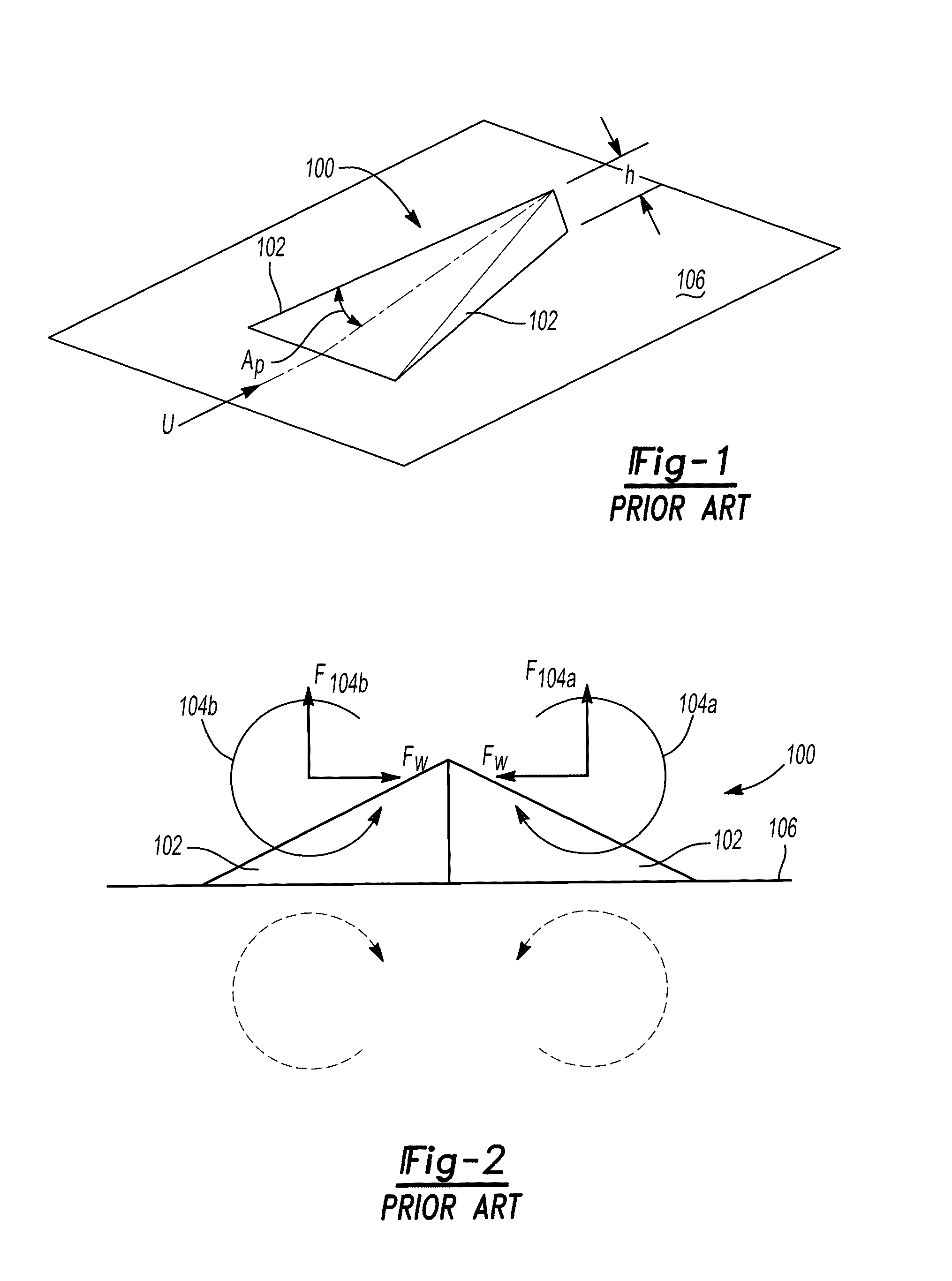
This in turn causes the vortices to quickly lift out of the boundary layer, reducing their efficacy in controlling the boundary layer.
Moreover, the effect of the wall on the resulting streamwise vortices is a further Biot-Savart induced interaction with their image vortices that causes the vortices 104a, 104b to move toward each other and thereby reduce their strengths through interdiffusion, thus further reducing their efficacy in controlling the boundary layer.
It is both these aspects of such prior art embedded passive boundary layer control devices that limit their efficacy, and that the disclosed new devices are able to overcome to achieve substantially greater efficacy.

Method used


Image

  • Passive boundary layer control elements
  • Passive boundary layer control elements
  • Passive boundary layer control elements

Examples


Embodiment Construction

[0056]Example embodiments will now be described more fully with reference to the accompanying drawings. Example embodiments are provided so that this disclosure will be thorough, and will fully convey the scope to those who are skilled in the art. Numerous specific details are set forth such as examples of specific components, devices, and methods, to provide a thorough understanding of embodiments of the present disclosure. It will be apparent to those skilled in the art that specific details need not be employed, that example embodiments may be embodied in many different forms and that neither should be construed to limit the scope of the disclosure.

[0057]The terminology used herein is for the purpose of describing particular example embodiments only and is not intended to be limiting. As used herein, the singular forms “a”, “an” and “the” may be intended to include the plural forms as well, unless the context clearly indicates otherwise. The terms “comprises,”“comprising,”“includ...


PUM


Abstract

Sub-boundary-layer-scale ramp-like vortex generators that can be mounted on any surface such as the wing of an airplane, the inlet to a propulsion system, the hull of a ship, or any other surface over which a fluid moves, when the objective is to minimize drag, irreversibility losses, or other performance penalties that can occur for reasons such as boundary layer separation or other undesirable boundary layer properties. The disclosed devices acts to passively induce streamwise vortices in the boundary layer, thereby transferring high-momentum fluid toward the surface in such a way as to alter the shape of the velocity profile within the boundary layer and thereby avoid or delay separation or alter other properties of the boundary layer.

Description

CROSS-REFERENCE TO RELATED APPLICATIONS[0001]This application claims the benefit of U.S. Provisional Application No. 61 / 164,699, filed on Mar. 30, 2009 and U.S. Provisional Application No. 61 / 211,540, filed on Mar. 31, 2009. The entire disclosure of each of the above applications is incorporated herein by reference.GOVERNMENT INTEREST[0002]This invention was made with government support under Grant No. FA8650-06-2-2625 awarded by the U.S. Air Force Research Laboratory. The government has certain rights in the invention.FIELD[0003]The present disclosure relates to vortex generators and, more particularly, relates to passive boundary layer control elements having a pair of cooperating micro ramps inducing vortices in a fluid that remain adjacent to a surface in response to their mutual Biot-Savart induced interaction.BACKGROUND AND SUMMARY[0004]This section provides background information related to the present disclosure which is not necessarily prior art. This section also provides ...

Claims


Application Information

Patent Timeline
Patent Type & Authority Patents(United States)
IPC IPC(8): B64C23/06B64C21/10
CPCB64C21/10F02C7/04Y10T137/8593F05B2240/923F05B2240/931F05D2270/17Y02T50/166F05D2270/42F05D2220/323F05D2250/11F05D2240/127F05D2250/21B64C2230/26Y10T137/2093B64D2033/0226Y02T50/10
Inventor DAHM, WERNER J. A.LAPSA, ANDREW P.
Owner RGT UNIV OF MICHIGAN
Learn More