Printing device and printing method

a printing device and printing method technology, applied in printing, other printing apparatus, etc., can solve the problem of no longer substantial gloss, and achieve the effect of increasing the gloss of ink containing metal fragments

Active Publication Date: 2013-09-10
SEIKO EPSON CORP
View PDF9 Cites 9 Cited by
  • Summary
  • Abstract
  • Description
  • Claims
  • Application Information

AI Technical Summary

Benefits of technology

[0007]The present invention was devised in view of such circumstances, and an object thereof is to increase the glossiness of ink containing metal fragments.

Problems solved by technology

The reflected light of the metal fragments distributed with irregular orientations then heads in irregular directions, and the glossiness is no longer considerably sufficient.

Method used


Image

  • Printing device and printing method
  • Printing device and printing method
  • Printing device and printing method

Examples


embodiments

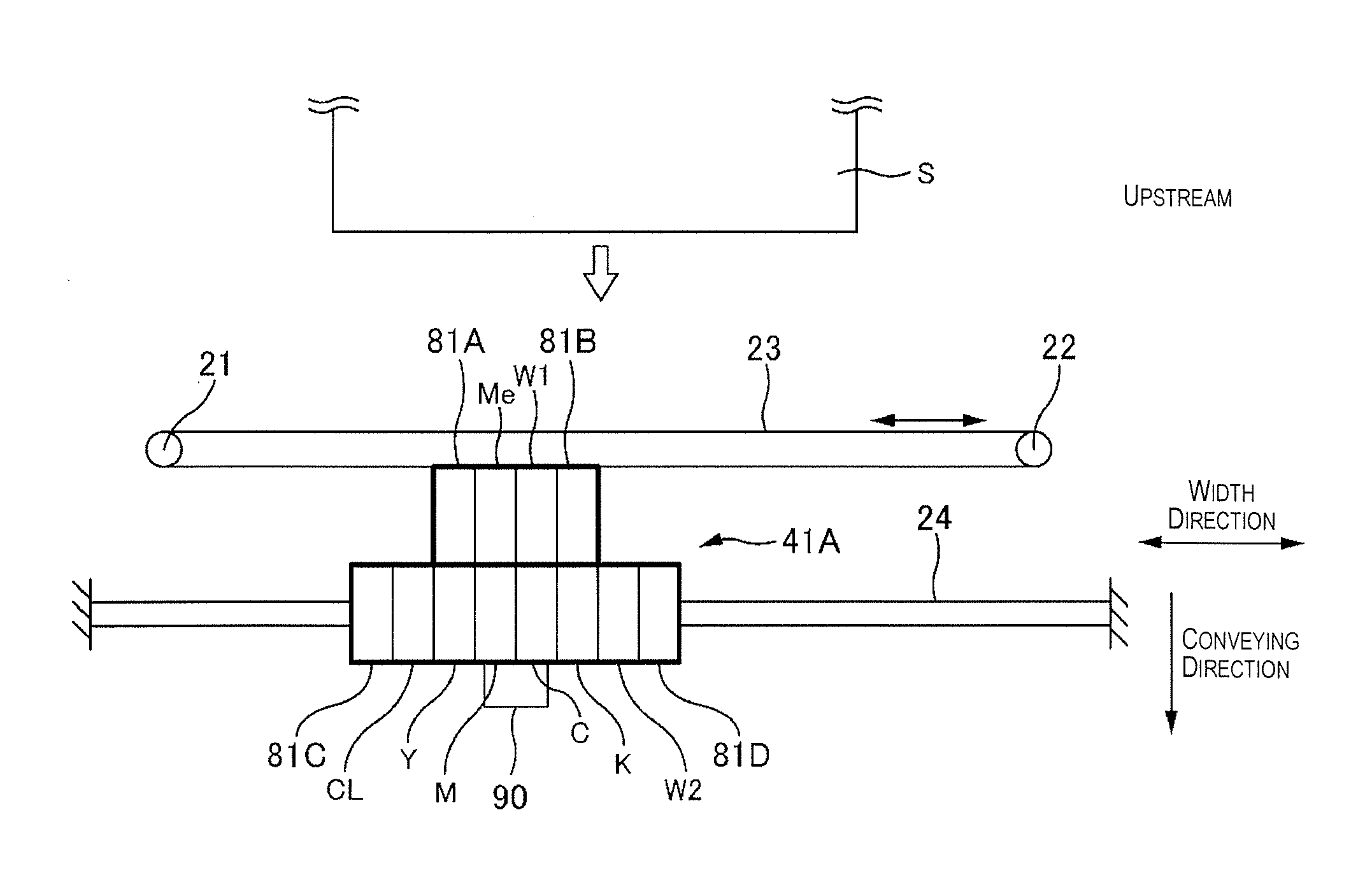
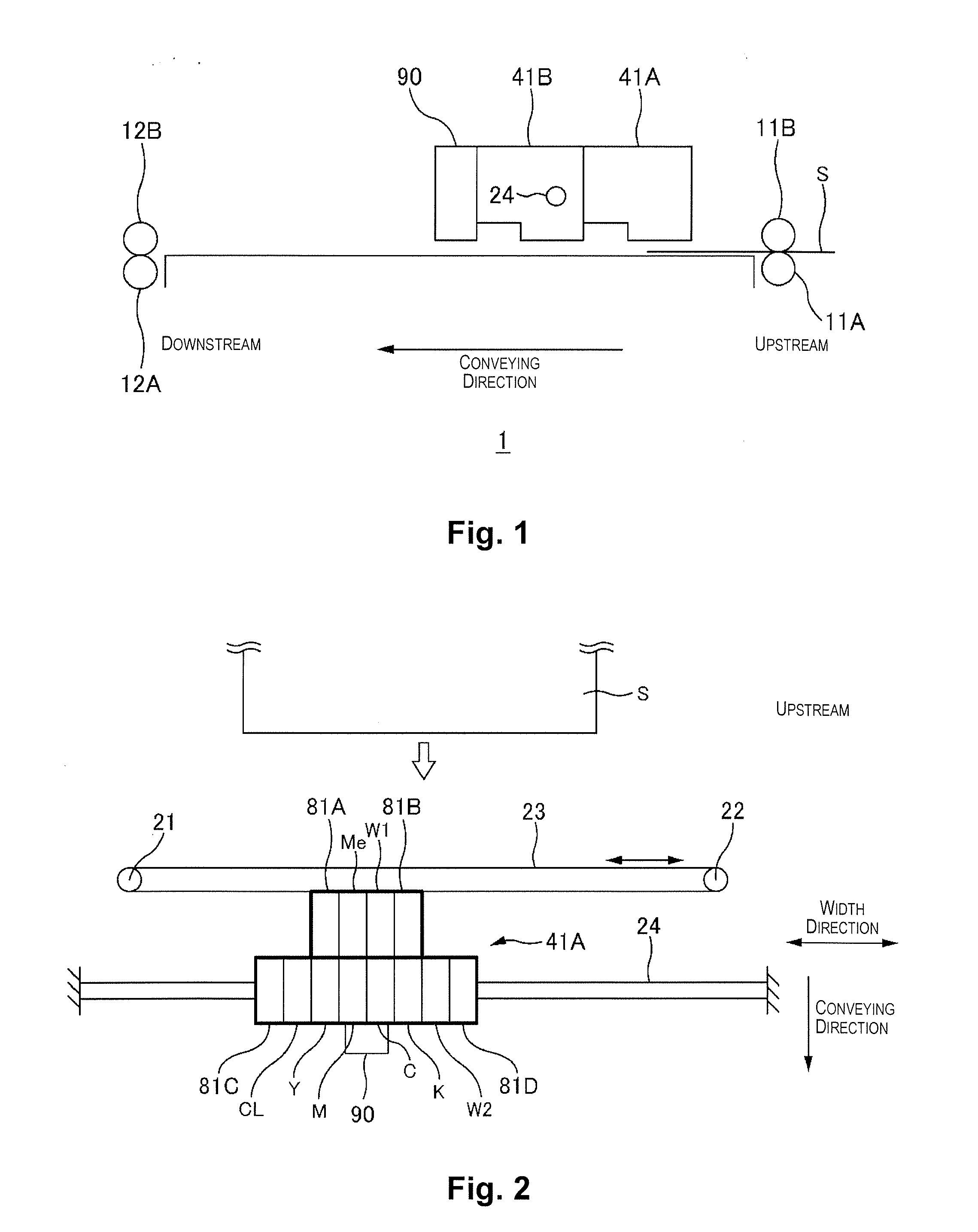
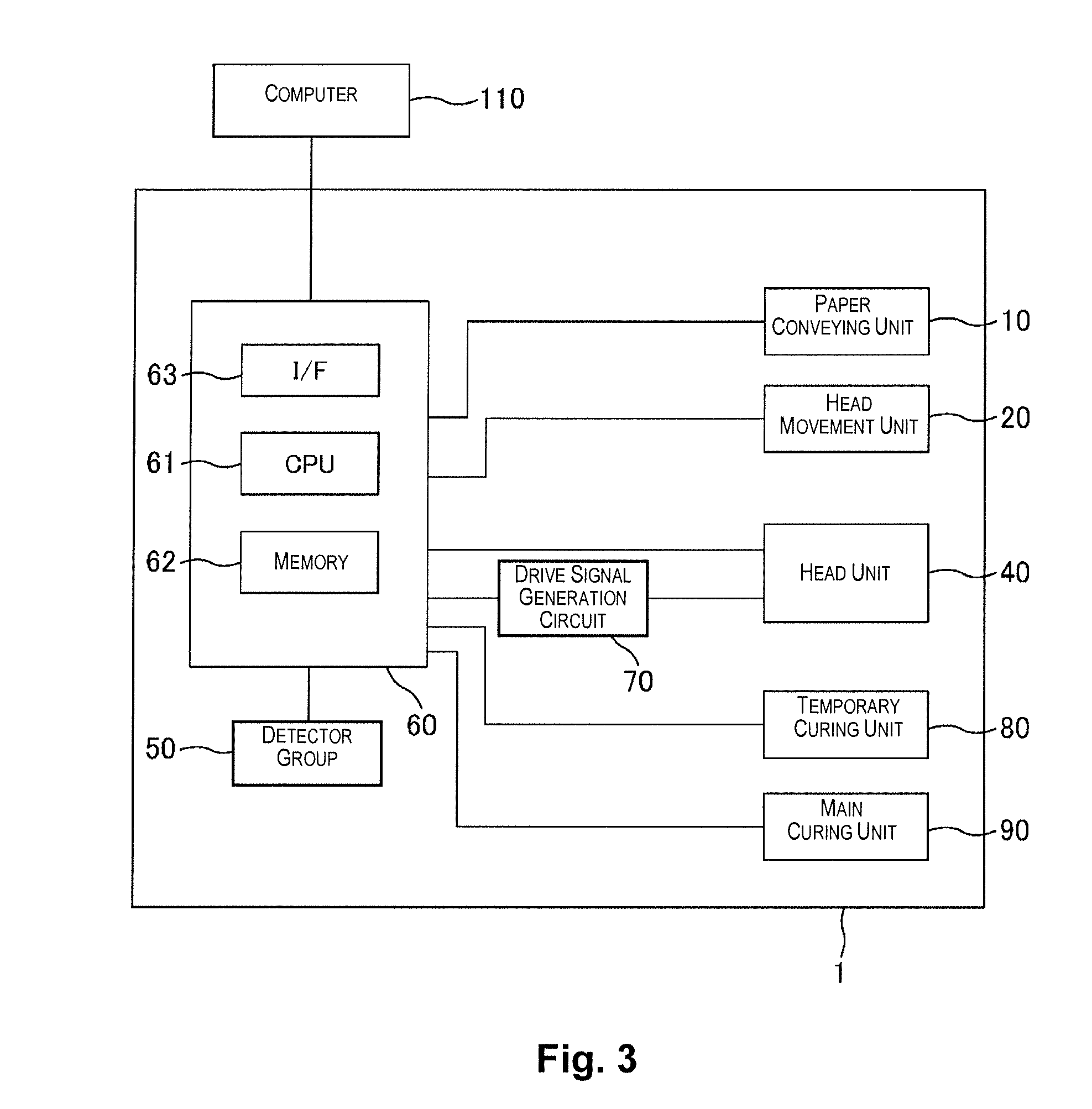
[0035]FIG. 1 is a schematic side view of the printer 1 in the present embodiment. FIG. 2 is a schematic top view of the printer 1 in the present embodiment. FIG. 3 is a block diagram of the printer 1 in the present embodiment. The configuration of the printer 1 is described hereinbelow with reference being made to these diagrams.

[0036]FIG. 3 shows the printer 1 and the computer 110. The printer 1 comprises a paper conveying unit 10, a head movement unit 20, a head unit 40, a detector group 50, a controller 60, a drive signal generation circuit 70, a temporary curing unit 80, and a main curing unit 90.

[0037]The paper conveying unit 10 includes a conveying roller 11A, a first pressing roller 11B, a paper ejection roller 12A, and a second pressing roller 12B. The conveying roller 11A and the paper ejection roller 12A are connected to a motor (not shown), and the rotation of the motor is controlled by a controller 60. The medium is conveyed in the conveying direction by being sandwiched...


PUM


Abstract

A printing device includes a nozzle, a radiation unit and a control unit. The nozzle is configured to eject metallic ink including metal fragments onto a medium. The radiation unit is configured to irradiate the medium with light to temporarily cure the metallic ink. The control unit is configured to control irradiation of the light by the radiation unit so that a film thickness formed by the metallic ink is equal to or less than a length of a long side of the metal fragments when the metallic ink is temporarily cured on the medium.

Description

CROSS-REFERENCE TO RELATED APPLICATIONS[0001]This application claims priority to Japanese Patent Application No. 2010-061262 filed on Mar. 17, 2010. The entire disclosure of Japanese Patent Application No. 2010-061262 is hereby incorporated herein by reference.BACKGROUND[0002]1. Technical Field[0003]The present invention relates to a printing device and a printing method.[0004]2. Related Art[0005]Inkjet printers have been developed which perform printing by ejecting metallic ink containing metal fragments onto a medium. A glossy printed product can be formed because the metal fragments reflect incident light. Since color ink is also sometimes ejected over the metallic ink, ultraviolet curable inks are used for these inks and the inks are cured by exposure to ultraviolet rays in order to prevent color mixing (see, for example, Japanese Laid-Open Patent Publication No. 2008-239951).SUMMARY[0006]The metal fragments of the metallic ink are scattered and distributed in irregular position...

Claims


Application Information

Patent Timeline
Patent Type & Authority Patents(United States)
IPC IPC(8): B41J29/38
CPCB41J11/002B41J11/0015B41J2/2114B41J11/00212B41J11/00214
Inventor ONISHI, HIROYUKI
Owner SEIKO EPSON CORP
Why Eureka
Try Eureka