Electrochromic display element

a display element and electrochromic technology, applied in the field of electrochromic display elements, can solve the problems of high difficulty in multi-color display, problematic slow response speed etc., and achieve the effect of reducing image blur and high-speed response of color developing or erasing

Active Publication Date: 2013-09-10
RICOH KK
View PDF18 Cites 13 Cited by
  • Summary
  • Abstract
  • Description
  • Claims
  • Application Information

AI Technical Summary

Benefits of technology

[0018]The present invention aims to solve the existing problems and achieve the following objects. That is, an object of the present invention is to provide an electrochromic display element in which an electrochromic compound exhibits high-speed response of color developing or erasing as well as image blur is reduced.
[0042]The present invention can provide an electrochromic display element in which an electrochromic compound exhibits high-speed response of color developing or erasing as well as image blur is reduced. This electrochromic display element can solve the existing problems.

Problems solved by technology

Any of these display devices, however, has much difficulty in performing multi-color display while ensuring white reflectance and contrast ratio.
The electrochromic display elements, however, have problematically slow response speed of color developing or erasing, since they develop or erase color utilizing oxidoreduction reaction.
However, by controlling the voltage, this multi-color display device can develop one color but cannot develop several colors simultaneously, since the electrochromic compounds stacked in the multi-color display device are compounds that develop different colors at different voltages.
The display device according to this proposal can develop several colors simultaneously, but requires complicate control of the voltage or current to selectively develop any color, since the display device has several kinds of electrochromic compounds that develop different colors.
However, use of an electrolyte prepared by dissolving a supporting electrolyte in a solvent, as described in prior arts, causes charges to be diffused in the electrolyte from the electrochromic compound developing color, leading to problematic image blur; i.e., bleeding due to spread of color-developing portions which occurs over time when the nearby electrochromic compounds not developing color also cause color-developing reaction.

Method used


Image

  • Electrochromic display element
  • Electrochromic display element
  • Electrochromic display element

Examples


first embodiment

[0045]An electrochromic display element of the present invention includes a display substrate, a display electrode, an electrochromic layer, an electrolyte layer, a counter electrode and a counter substrate; and, if necessary, further includes other members.

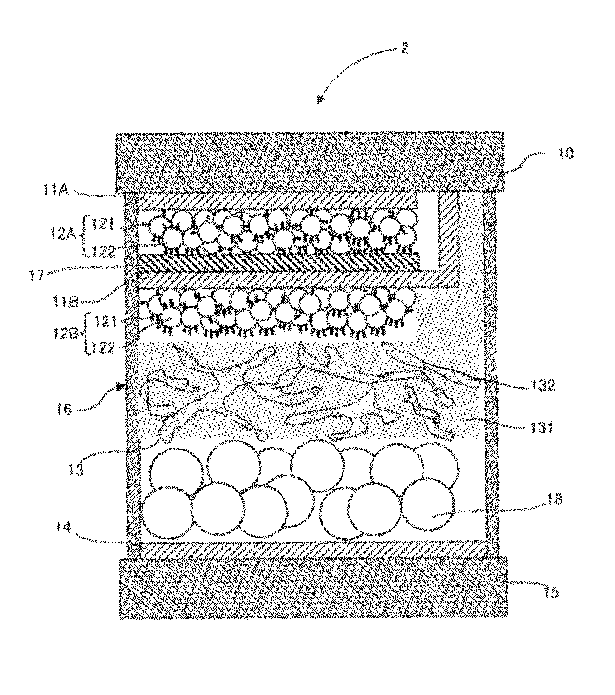
[0046]As shown in FIG. 1, an electrochromic display element 1 according to a first embodiment of the present invention includes a counter substrate 15, a counter electrode 14, an electrolyte layer 13, an electrochromic layer 12, a display electrode 11 and a display substrate 10, which are laminated in this order.

>

[0047]The display substrate 10 is a substrate for supporting the display electrode 11. The counter substrate 15 is a substrate for supporting the counter electrode 14. The material of the display substrate 10 or the counter substrate 15 is not particularly limited and may be appropriately selected depending on the intended purpose, so long as at least one of the display substrate 10 and the counter substrate 15 is made o...

second embodiment

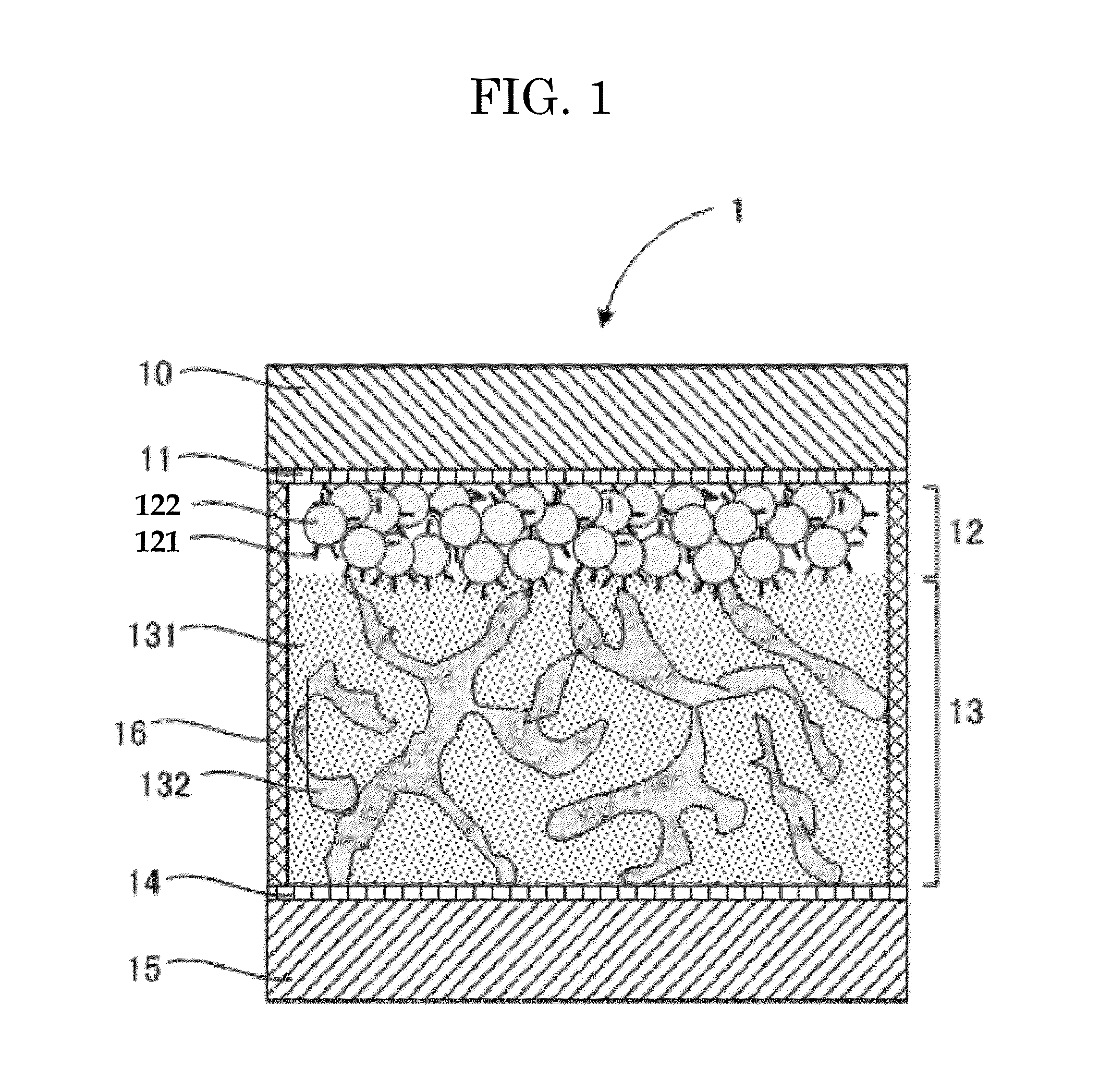
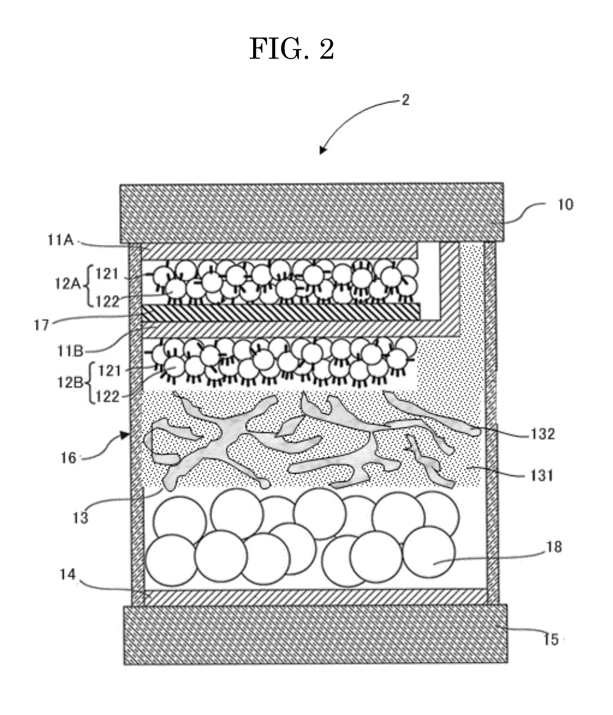
[0104]As shown in FIG. 2, an electrochromic display element 2 according to a second embodiment of the present invention is the same as that according to the first embodiment, except that at least two display substrates 11 and at least two electrochromic layers 12 are provided. The same explanation as in the first embodiment is omitted as appropriate.

[0105]As shown in FIG. 2, the electrochromic display element 2 of the present invention includes a counter substrate 15, a counter electrode 14, an electrolyte layer 13, a second electrochromic layer 12B, a second display electrode 11B, an insulating layer 17, a first electrochromic layer 12A, a first display electrode 11A and a display substrate 10, which are laminated in this order; and, if necessary, further include other layers.

[0106]Also, the electrochromic display element 2 may have the cell 16 containing the display substrate 10 and the counter substrate 15 attached to each other via a spacer.

>

[0107]The first display electrode 11A...

synthesis example 1

Preparation of Electrolyte Layer Precursor Material

[0145]A propylene carbonate solution of hyperchloric acid tetrabutylammonium salt (serving as an electrolyte) (concentration: 2 mol / L), was mixed with PNM-170 (product of DIC Corporation) containing a liquid crystal compound for PNLC, a polymerizable monomer and a polymerization initiator.

[0146]The concentration of the propylene carbonate solution of hyperchloric acid tetrabutylammonium salt was adjusted to be about 0.04 mol / L. Also, 0.2% by mass of spherical resin beads (weight average particle diameter: 10 μm) was dispersed in the resultant mixture for controlling the average thickness of the formed electrolyte layer, to thereby prepare an electrolyte layer precursor material.


PUM

PropertyMeasurementUnit
light transmittanceaaaaaaaaaa
particle diameteraaaaaaaaaa
thicknessaaaaaaaaaa

Abstract

An electrochromic display element including a display substrate, at least one display electrode, a counter electrode, a counter substrate, at least one electrochromic layer in contact with the display electrode, and an electrolyte layer between the electrochromic layer and the counter electrode, wherein the electrolyte layer contains a matrix resin having a three-dimensionally crosslinked structure and a mixture of a liquid crystal compound and an electrolyte, and wherein the mixture of the liquid crystal compound and the electrolyte is dispersed as a continuous phase in the matrix resin.

Description

BACKGROUND OF THE INVENTION[0001]1. Field of the Invention[0002]The present invention relates to an electrochromic display element in which an electrochromic compound exhibits high-speed response of color developing or erasing as well as image blur is reduced.[0003]2. Description of the Related Art[0004]In recent years, development has extensively been made on electronic paper as a medium in place of paper. Electronic paper is a display device used like paper, and thus needs to meet requirements different from those for conventional display devices such as CRTs and liquid crystal displays. For example, electronic paper is required to have high white reflectance, high contrast ratio, high-definition display performance and display memory effect as well as to be thin, light, inexpensive and able to drive at even low voltages. Of these, white reflectance and contrast ratio that are comparable to those of paper are highly required, since these requirements influence the display quality ...

Claims


Application Information

Patent Timeline
Patent Type & Authority Patents(United States)
IPC IPC(8): G02F1/153
CPCG02F1/1334G02F1/1525G02F2001/1519G02F2001/133337G02F2001/164G02F1/133337
Inventor FUJIMURA, KOHHIRANO, SHIGENOBUYASHIRO, TOHRUNAIJO, YOSHIHISA
Owner RICOH KK
Why Eureka
Try Eureka