Method and system for providing a read transducer having a composite magnetic shield with smooth interfaces

a composite magnetic shield and read transducer technology, applied in the field of methods and systems, can solve the problems of introducing noise, and unstable magnetic shield b>20/b>, and affecting the performance of the conventional read transducer

Active Publication Date: 2013-09-10
WESTERN DIGITAL TECH INC
View PDF17 Cites 191 Cited by
  • Summary
  • Abstract
  • Description
  • Claims
  • Application Information

AI Technical Summary

Benefits of technology

[0004]A method and system provide a magnetic transducer having an air-bearing surface (ABS). The magnetic transducer includes a first shield, a read sensor, magnetic bias structure(s) and a second shield. The read sensor includes edge(s) which are adjacent to the magnetic bias structure(s). The read sensor and the magnetic bias structure(s) are between the first shield and the second shield. The second shield includes a first ferromagnetic layer, a nonmagnetic spacer layer, a second ferromagnetic layer and a pinning layer. The nonmagnetic spacer layer is between the first ferromagnetic layer and the second ferromagnetic layer. The first ferromagnetic layer is between the read sensor and the nonmagnet

Problems solved by technology

In particular, the magnetic moment of the shield 20 may be unstable.
Movement of domain walls and other changes to the magnetic

Method used


Image

  • Method and system for providing a read transducer having a composite magnetic shield with smooth interfaces
  • Method and system for providing a read transducer having a composite magnetic shield with smooth interfaces
  • Method and system for providing a read transducer having a composite magnetic shield with smooth interfaces

Examples


Embodiment Construction

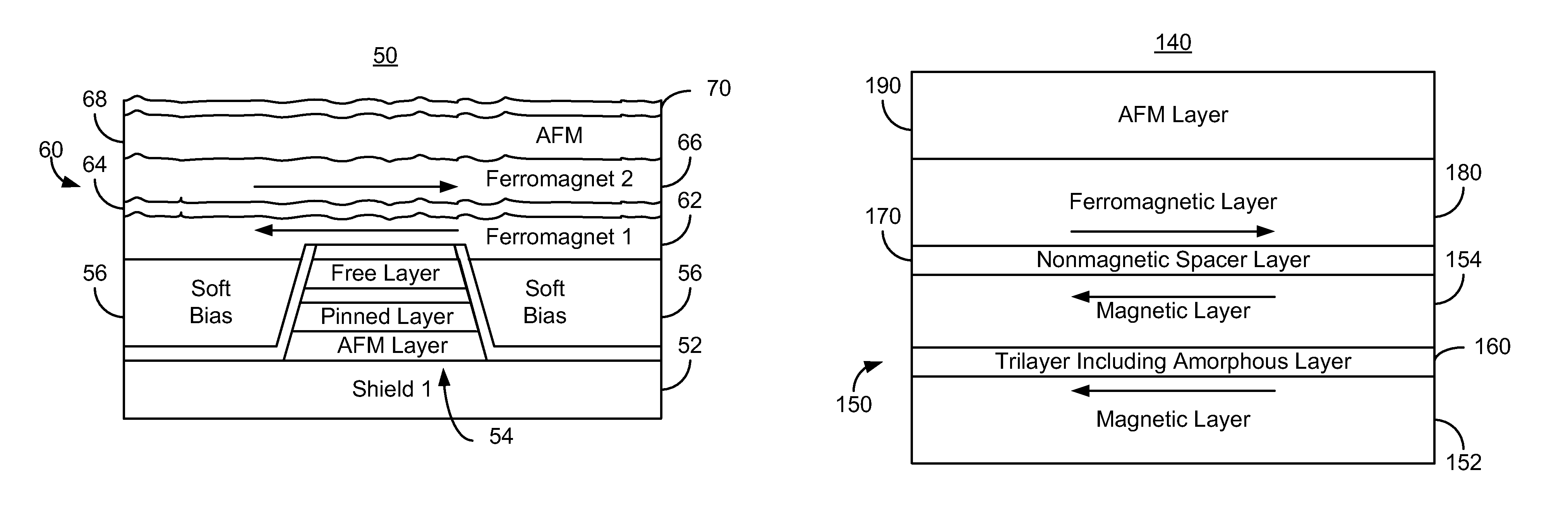
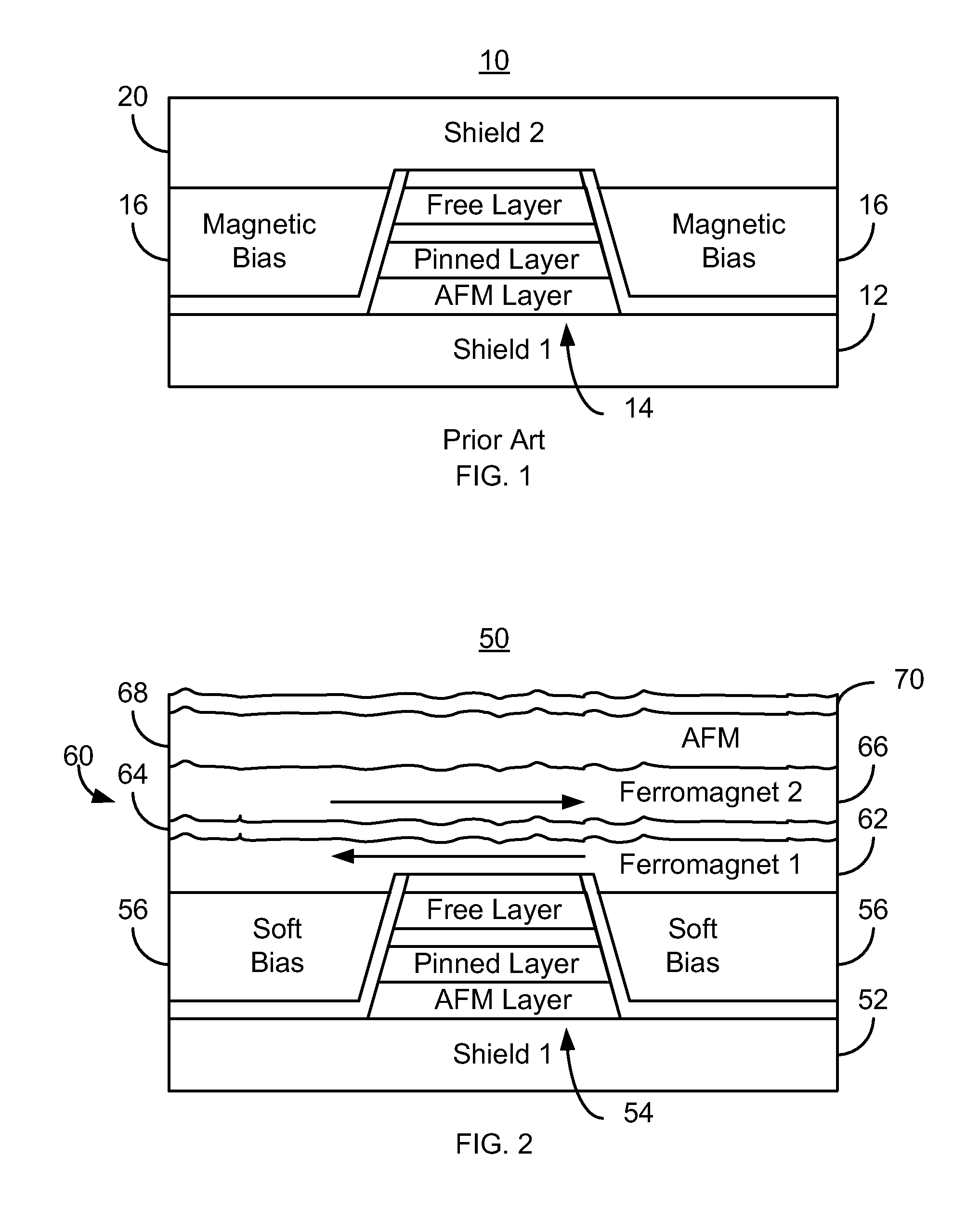
[0016]FIG. 2 depicts an ABS view of a portion of a more recent magnetic read transducer 50. For clarity, FIG. 2 is not to scale. The read transducer 50 may be part of a read head or may be part of a merged head that also includes a write transducer. The transducer 50 includes shields 52 and 60, a read sensor 54 and soft magnetic bias structures 56. The sensor 54 shown is a GMR or TMR sensor. Thus, the sensor 54 includes a pinning layer, a pinned, a nonmagnetic spacer layer, a free layer, and a capping layer. For simplicity, these layers are not separately labeled in FIG. 2. The sensor 54 may also include seed layer(s) (not shown). Although an AFM layer used to pin the magnetic moment of the pinned layer is shown, in other embodiments, the pinning layer may be omitted or may use a different pinning mechanism. The pinned layer and free layer are each shown as a single layer, but may include multiple layers including but not limited to a synthetic antiferromagnetic (SAF) structure. The...


PUM


Abstract

A method and system provide a magnetic transducer including first and second shields, a read sensor, and magnetic bias structure(s) adjacent to the read sensor. The read sensor and magnetic bias structure(s) are between the shields. The second shield includes first and second ferromagnetic layers, a nonmagnetic spacer layer and a pinning layer. The nonmagnetic spacer layer is between the first and second ferromagnetic layers. The first ferromagnetic layer is between the read sensor and the nonmagnetic spacer layer. The pinning layer is adjacent to the second ferromagnetic layer. The first and second ferromagnetic layers are coupled antiparallel. The first ferromagnetic layer includes magnetic layers interleaved with trilayer(s). Each magnetic layer includes crystalline grains. The trilayer(s) include an amorphous nonmagnetic layer less than three Angstroms thick. Thus, the magnetic layers are ferromagnetically coupled but the crystalline grains in different magnetic layers are decoupled.

Description

BACKGROUND[0001]FIG. 1 depicts an air-bearing surface (ABS) view of a conventional read transducer 10. The conventional read transducer 10 includes shields 12 and 20, sensor 14 and magnetic bias structures 16. The read sensor 14 is typically a giant magnetoresistive (GMR) sensor or tunneling magnetoresistive (TMR) sensor. The read sensor 14 includes an antiferromagnetic (AFM) layer, a pinned layer, a nonmagnetic spacer layer, and a free layer. Also shown is a capping layer. In addition, seed layer(s) may be used. The free layer has a magnetization sensitive to an external magnetic field. Thus, the free layer functions as a sensor layer for the magnetoresistive sensor 14. The magnetic bias structures 16 may be hard bias structures or soft bias structures 16. These magnetic bias structures are used to magnetically bias the sensor layer of the sensor 14.[0002]Although the conventional transducer 10 functions, there are drawbacks. In particular, the magnetic moment of the shield 20 may ...

Claims


Application Information

Patent Timeline
IPC IPC(8): G11B5/39
CPCG11B5/3909B82Y10/00G11B5/3932G11B2005/3996
Inventor XIAO, RONGFUGUO, YIMIN
Owner WESTERN DIGITAL TECH INC
Why Eureka
Try Eureka