Gearbox noise reduction by electrical drive control

a technology of electrical drive and noise reduction, applied in the direction of underwater vessels, amplifier modifications, non-deflectable wheel steering, etc., can solve the problems of difficulty in accurately pinpointing the exact source of audible noise, and various forms of passive and active noise cancellation schemes have been used to reduce or eliminate low frequency noise with limited success. , to achieve the effect of reducing the audible nois

a technology of electrical drive and noise reduction, applied in the direction of underwater vessels, amplifier modifications, non-deflectable wheel steering, etc., can solve the problems of difficulty in accurately pinpointing the exact source of audible noise, and various forms of passive and active noise cancellation schemes have been used to reduce or eliminate low frequency noise with limited success. , to achieve the effect of reducing the audible nois

US8532828B2Active Publication Date: 2013-09-10GENERAL ELECTRIC CO

Image

  • Gearbox noise reduction by electrical drive control
  • Gearbox noise reduction by electrical drive control
  • Gearbox noise reduction by electrical drive control

Examples


Embodiment Construction

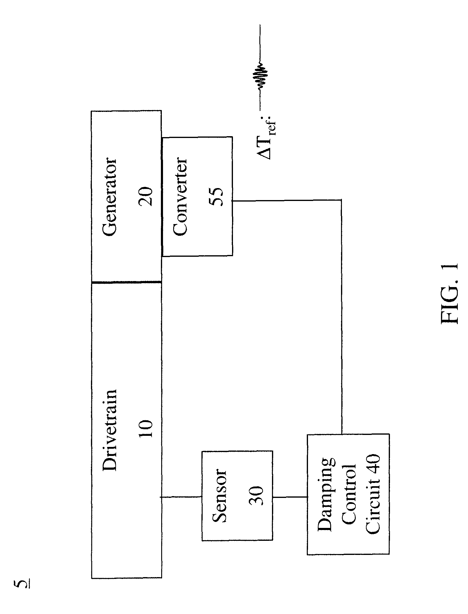
[0027]In general, certain embodiments of the invention provide for a reduction of noise issues with systems employing drive trains. An example of a drive train refers to those systems using gearboxes. As used herein, gearboxes shall include the various forms of transmissions and drive trains that experience noise and vibration issues.

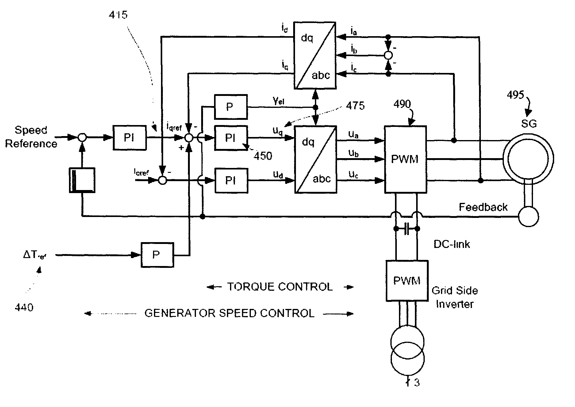
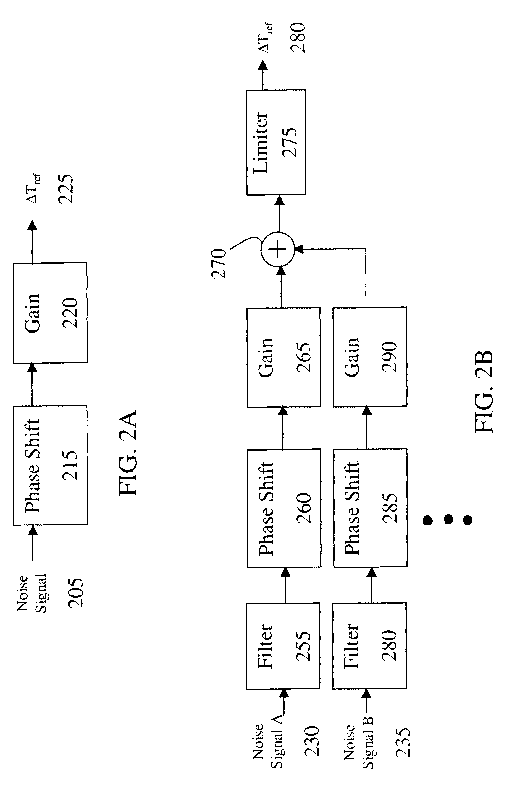
[0028]According to one embodiment, the noise reduction is achieved by suppressing the effect of the noise excitation, such as the gear-mesh excitation, by using a noise reduction control circuit for the drive system. The noise reduction circuit generates a dynamic torque feedback signal with the same frequency as the noise signal but at a different phase, wherein the feedback signal is fed back to the air-gap torque of the system, such as electric motor or generator. As used herein, electric machine shall refer to the various motors and generators that can be coupled to a drive train.

[0029]Many electrical drives are operated at variable frequency, such ...


PUM


Abstract

A system for damping audible noise from a drive train. One embodiment is a system with an audible noise signal from a drive train wherein a damping circuit produces a damping torque that is a phase shifted and amplified version of the noise signal that is applied to the air-gap torque of a generator or motor coupled to the drive train and effectively reduces the audible noise.

Description

FIELD OF THE INVENTION[0001]The invention relates generally to noise reduction, and more particularly to the reduction of noise in electrical drives.BACKGROUND OF THE INVENTION[0002]There are numerous studies concerning the effects of low frequency noise on humans. While the results are somewhat subjective with respect to the effects of such noise, there is a growing tendency to reduce noise effects from industrial sources wherever possible to maintain goodwill with the end users and the public. The term low frequency as used herein refers to noise in the audible frequency range from about 20 Hz to several hundred Hertz. For reference purposes, the hearing range of most humans is typically about 20 Hz-20 KHz and termed the audible frequency range.[0003]For reference purposes, the article prepared by the Renewable Energy Research Laboratory, Dept. of Mechanical and Industrial Engineering, University of Amherst (June 2002) entitled “Wind Turbine Acoustic Noise” describes the general n...

Claims


Application Information

Patent Timeline
10 Sep 2013
Publication
US8532828B2
IPC
G05B21/00; H03F1/26; H04B15/00; G10K11/16; B62D5/04; F16H57/00; G01R29/26; G05D19/02; G10K11/178
CPC
F16H57/0006; G05D19/02; B62D5/0463; G10K2210/1282; G10K11/1788; G01R29/26
Inventors
SCHRAMM, SIMON; SIHLER, CHRISTOF