
Shutter drive apparatus

Inactive Publication Date: 2013-09-17
STONE LAWRENCE MATTHEW
View PDF18 Cites 12 Cited by
  • Summary
  • Abstract
  • Description
  • Claims
  • Application Information

AI Technical Summary

Benefits of technology

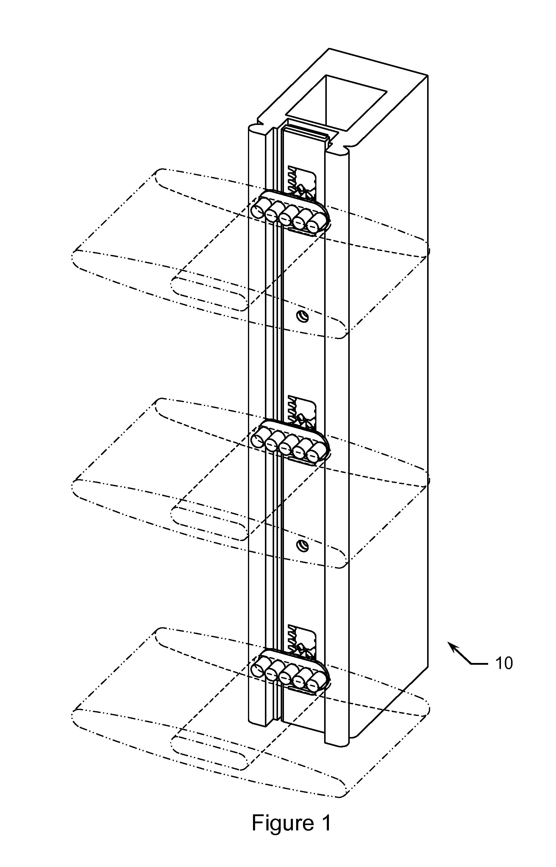
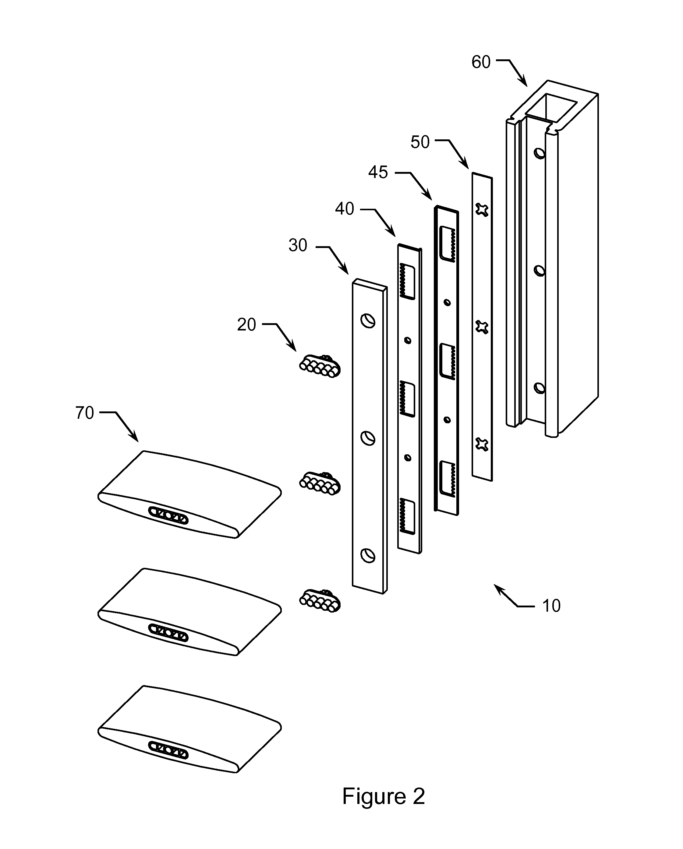
The invention is a shutter drive apparatus that allows for the movement of one shutter louver to result in the corresponding movement of all the other shutter louvers. The shutter is a tilt-rod-less shutter and includes a frame with top and bottom horizontal rails and side stiles. The louvers are mounted within the stiles and can rotate freely. The shutter drive apparatus is mounted within the second stile and includes pinion gears, a face strip, drive strips, and a retainer strip. Each louver is engaged with a different pinion gear, and each pinion gear is engaged with the drive strips. This results in a chain of movement where the movement of one shutter louver results in the movement of all the other shutter louvers. The shutter drive apparatus is designed to require minimal parts and has a low manufacturing cost.

Problems solved by technology

While such use of shutters have been both decorative and functional, a problem with many such shutters is that the tilt rod used to position the louvers of such shutters has restricted the range of motion of such louvers such that the louvers of the shutter are not completely closeable.
However, in such “tilt-rod-less” configurations, unless each louver is to be separately adjustable (a very cumbersome and impractical configuration), a drive mechanism is required such to adapt the shutter such that the movement of (any) one shutter louver (e.g. the opening or closing of one louver) results in the corresponding movement (slaved movement) of all of the shutter louvers.

Method used


Image

  • Shutter drive apparatus
  • Shutter drive apparatus
  • Shutter drive apparatus

Examples


first embodiment

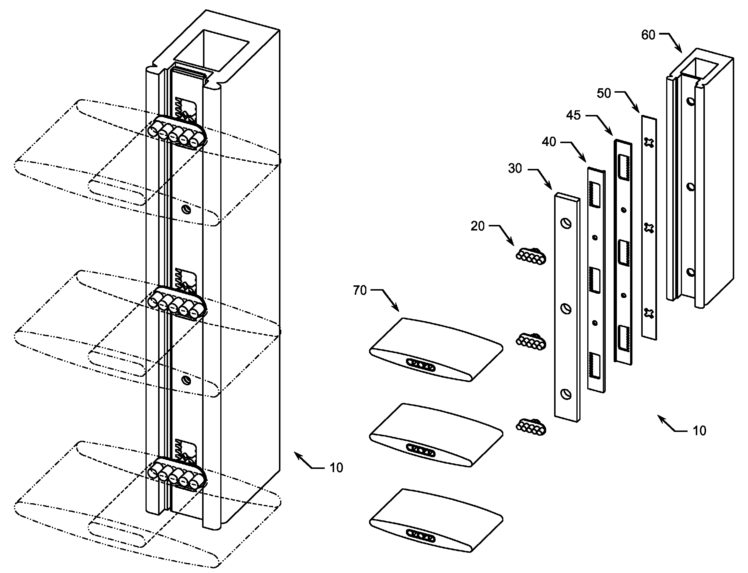
[0028]Referring now to the drawings and in particular to FIGS. 1 through 12, the invention is a shutter drive apparatus 10 comprising a pinion gear 20, a face strip 30, a first drive strip 40, a second drive strip 45, and a retainer strip 50. Pinion gear 20 defines a preferably injection molded plastic gear having an engagement cleat 22 having a plurality of prongs 23, a bearing surface 24, a gear 26, and an axle 28. Face strip 30 defines a substantially elongated generally rectangular strip having a plurality of gear reception sockets 32. Face strip 30 may for instance be formed from wood, plastic, metal (e.g. aluminum) or, a composite thereof. Drive strip 40 defines a substantially generally elongated rectangular strip having general “L” cross-sectional shape and having a load flange 41, a plurality of drive openings 42, each drive opening 42 having a plurality of drive teeth 43, and a plurality of punch indexing holes 44. Drive strip 40 is preferably formed from an aluminum extru...

second embodiment

[0031]Referring now to the drawings and in particular to FIGS. 13 through 17, the invention is a shutter drive apparatus 100 comprising a pinion gear 20, a front case member 110, a first drive strip 40, a second drive strip 45, a retainer strip 50, and a rear case member 120. Front case member 110 defines a substantially generally elongated rectangular member having general “C” cross-sectional shape and having a plurality of gear reception sockets 112 and a plurality of engagement grooves 114. Front case member 110 is preferably formed from an aluminum extrusion. Rear case member 120 defines a substantially generally elongated rectangular member having general “C” cross-sectional shape and having a plurality of gear reception sockets 122 and a plurality of engagement ridges 124. Rear case member 120 is preferably formed from an aluminum extrusion.

[0032]Shutter drive apparatus 100 is assembled such that pinion gears 20 are inserted into gear reception sockets 112 of front case member...


PUM


Abstract

The shutter drive apparatus is an apparatus adapted such that the movement of any one shutter louver of a tilt-rod-less shutter results in the corresponding movement of all of the louvers of the shutter. The apparatus is preferably mounted within a tilt-rod-less shutter comprising a shutter frame having at least top and bottom horizontal rails, at least a first side stile and a second side stile, and a plurality of louvers rotatably mounted within the stiles such that a first end of the louvers are freely rotatable within the first side stile, and such that a second end of the louvers are drivably engaged to the apparatus. The apparatus includes a plurality of pinion gears, a face strip, opposing drive strips, and a retainer strip. Each louver is drivably engaged to a different pinion gear and each pinion gear is drivably engaged to the drive strips.

Description

CROSS REFERENCE TO RELATED APPLICATIONS[0001]This nonprovisional utility patent application claims the benefit under 35 USC §119(e) of U.S. provisional application No. 61 / 626,195 filed Sep. 22, 2011 and of U.S. provisional application No. 61 / 632,049 filed Jan. 17, 2012 both of which are incorporated, in their entirety, by this reference.BACKGROUND[0002]The present invention relates generally to window covering shutters such as plantation style shutters and their respective drive systems. More particularly, the present invention relates to “tilt-rod-less” shutters and drive systems that are adapted such that the movement of (any) one shutter louver (e.g. the opening or closing of one louver) results in the corresponding movement (slaved movement) of all of the shutter louvers.RELATED ART[0003]Window cover type shutters are well known and have long been used to not only improve home décor, but to allow for the amount and direction of light allowed to pass through a cover window and in...

Claims


Application Information

Patent Timeline
IPC IPC(8): E06B7/096E06B7/08
CPCE06B7/096
Inventor STONE, LAWRENCE MATTHEW
Owner STONE LAWRENCE MATTHEW
Learn More