Sealable drain pipe coupling

a drain pipe and coupling technology, applied in the direction of pipes, water closets, roof coverings, etc., can solve the problems of reducing the installation reducing the installation time of drain inserts, and reducing the reliability of seals, so as to reduce the time and effort of positioning the tool and installing the inserts. , the effect of reducing the installation tim

Active Publication Date: 2013-09-17
ABBASI ABDUL LATIF +1
View PDF4 Cites 7 Cited by
  • Summary
  • Abstract
  • Description
  • Claims
  • Application Information

AI Technical Summary

Benefits of technology

[0005]One object of the present device is to provide an easier method of installing a drain insert, by providing a large castle head, instead of individual screws. This reduces the time and effort to position the tool and install the insert. Another object of the present device is to allow for tightening the device with a single tightening operation, rather than multiple tightening operating of multiple screws. This reduces installation time and increases productivity, while eliminating the chance that one or more screws are left loose and undetected. Another object of the present device is to provide a better seal quality by tightening the cylinders uniformly towards each other with uniform compressive force on the seal material. Another object of the present device is to reduce the installation time and effort, thereby reducing installation cost. Another object of the present invention is to provide a device which is easier to manufacture and has small number of parts, as well as eliminating all metal parts.
[0009]Additionally, the apparatus may also include a means to prevent the assembly from unintentionally rotating and loosening after it is installed. In this embodiment of the invention, the said ring has indentations on at least one face, and the articulated housing has at least one bump on the inner face of its collar. Once the assembly is fully tightened, the indentations on the ring grip at least one bump on the collar. This feature makes the assembly hard to rotate once it is tight, and therefore prevents it from loosening due to vibration or any other means. However, the indentations or bumps may be located on any other part of the assembly as long as the said purpose is achieved. The indentations may also take the form of a ratchets that only allow the assembly to be rotated in one direction.
[0010]The present invention can be installed by only one tightening operation, and provides the convenience of easy location of the tightening tool. The prior art pipe sealing joints consisted of more than one fastener, and therefore required locating a screwdriver more than one time at each fastener location and tightening each to the same torque to ensure equal distribution of compressive / gripping / sealing force. One or more screws not properly tightened during installation were easy to be left undetected and may have lead to seal failure.

Problems solved by technology

However, these types of seals are generally not reliable and there is a potential for the development of cracks and consequently leakage.
If one or more screws are not properly tightened during the installation, they may lead to seal failure.

Method used


Image

  • Sealable drain pipe coupling
  • Sealable drain pipe coupling
  • Sealable drain pipe coupling

Examples


Embodiment Construction

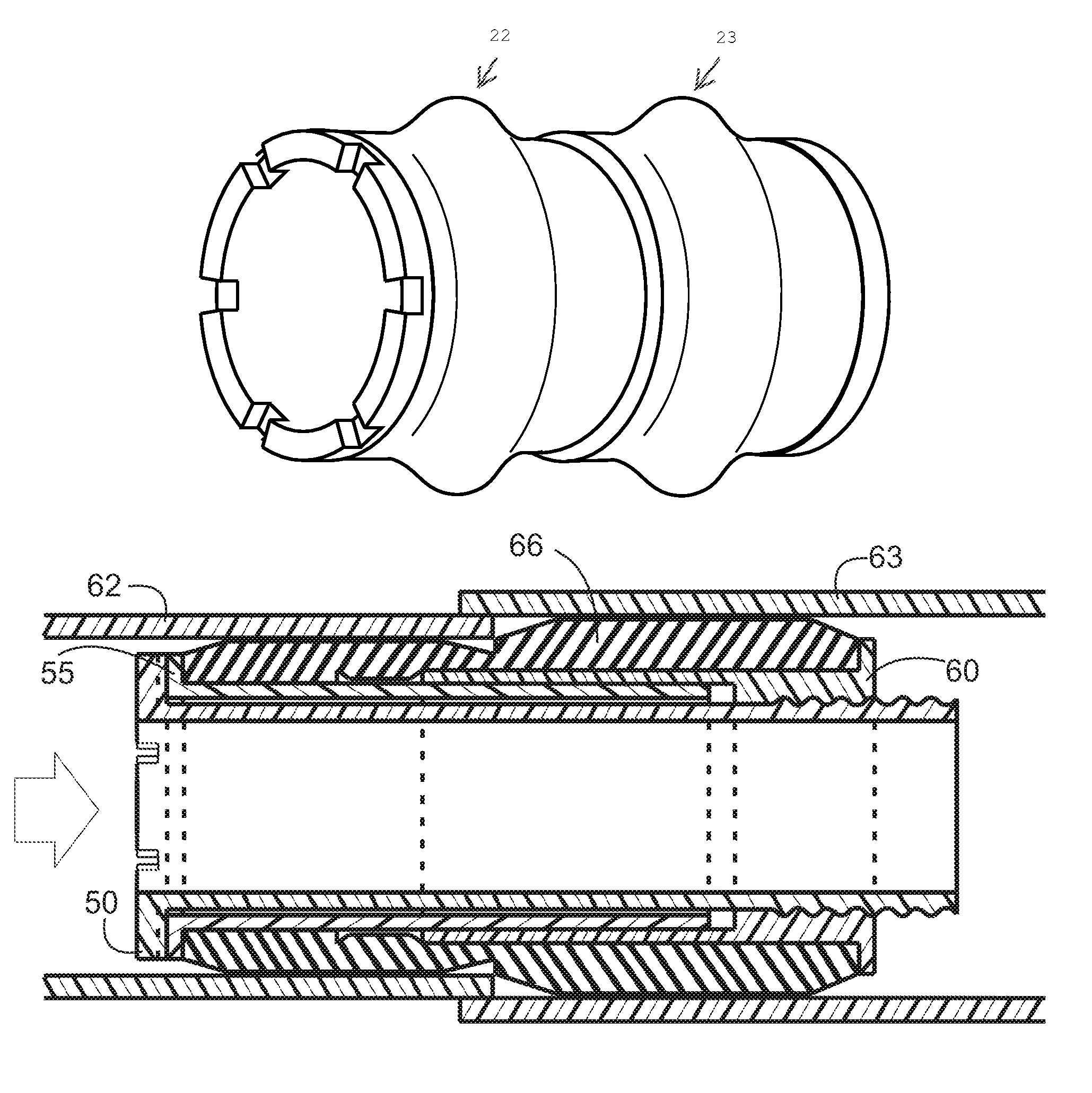
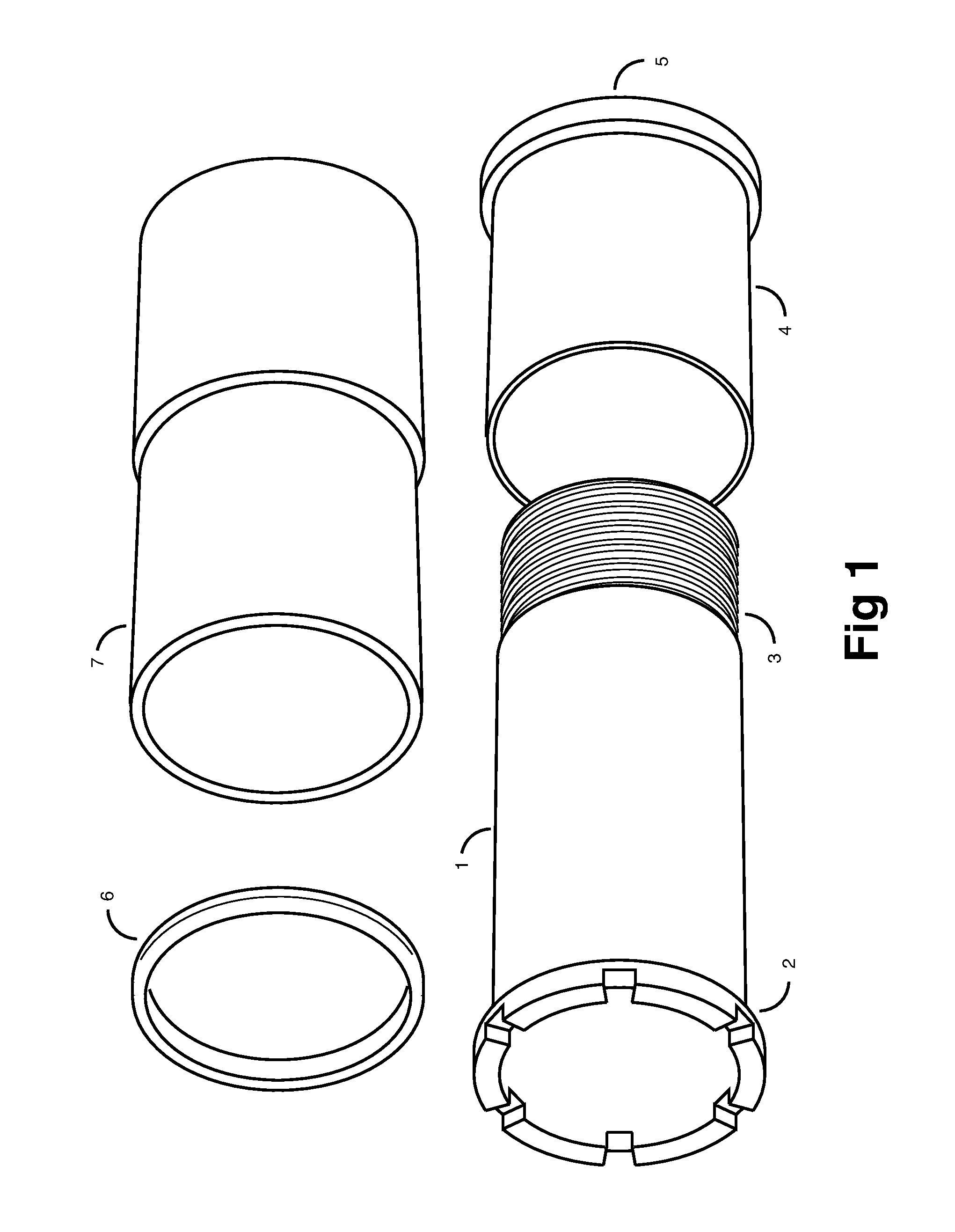
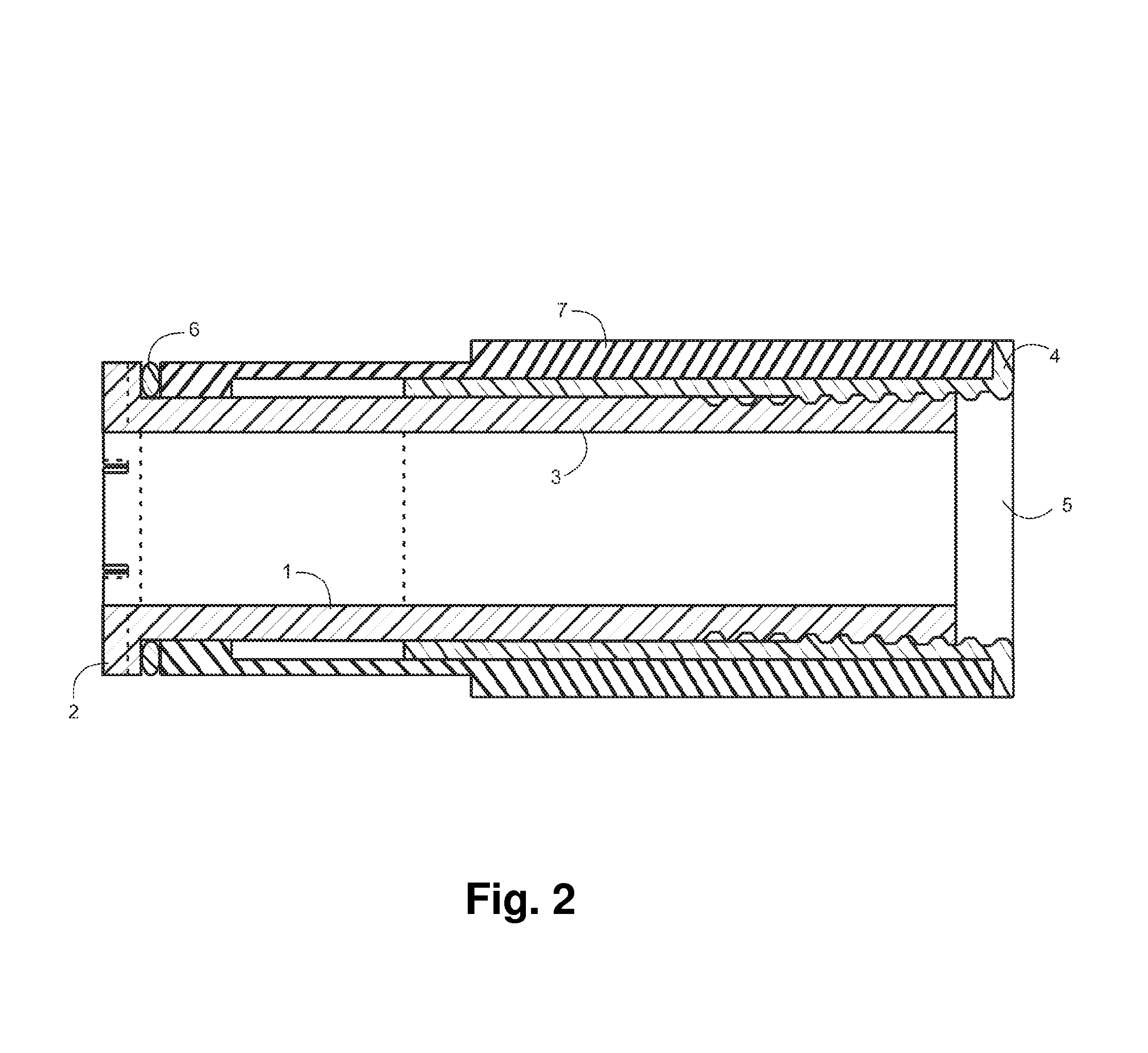
[0023]The present invention is a pipe coupling which forms a sealed joint between two concentric pipes. In particular, the present device is used for connecting a new pipe to an existing drain pipe of the type generally found on the roof tops. As FIGS. 1-3 show, the present invention is comprised of two solid tubular / cylindrical bodies 1 and 4, an elastic tubular body 7 of rubber or similar material, and a ring 6 to prevent the elastic material to grip and rotate with the rotating body 1. The tubular bodies 1 and 4 can be connected to each other by means of threads to form an articulated housing.

[0024]One end of the tubular body 1 has a collar 2. This collar is shaped as a castle head. The castle head shape allows for an easy access to the head using an appropriately shaped tool 8, as shown in FIG. 4. However, any other shape may be used to provide a mating head for the tightening tool 8. At the opposite end, the tubular body 1 consists of fastening threads 3 on the external side of...


PUM


Abstract

The present invention relates to an apparatus which forms a sealed joint between two pipes, particularly but not limited to roofing drain pipes. This apparatus includes a cylindrical body made of rubber or similar material that grips and seals two pipes when it is axially compressed by two halves of an articulated housing as they move towards each other. The two half bodies of the articulated housing are threaded to each other such that when one body is rotated in one direction, the bodies move towards each other, thereby reducing the overall length of the housing, and compressing / deforming the rubber seal.

Description

FIELD OF THE INVENTION[0001]The present invention relates to a coupling device that sealably connects a roof drain inserts inside a drain pipe. Sealed coupling devices are used to connect two pipes to each other and making sure that there will be no leaks.DESCRIPTION OF THE RELATED ART[0002]Many buildings have roof drains to remove rain or melted snow water. Roof drains are more common in flat top asphalt roofs. In many occasions, such as in resurfacing of a roof, the height of the roof may be increased. Therefore, the drain pipe has to be extended. One simple and low cost method of extending the drain pipe, without removing the whole pipe, is to tightly insert a smaller pipe into the drain pipe. The insert is then sealed using adhesives or caulking compounds. However, these types of seals are generally not reliable and there is a potential for the development of cracks and consequently leakage.[0003]An alternative to use of adhesives and caulking compounds is suggested by Uglow's i...

Claims


Application Information

Patent Timeline
Patent Type & Authority Patents(United States)
IPC IPC(8): F16L27/12
CPCE04D13/08F16L21/08E04D2013/0846
Inventor ABBASI, ABDUL LATIFYOUSUFZAI, JAMAL
Owner ABBASI ABDUL LATIF
Why Eureka
Try Eureka