
System and method for fast-acting power protection

a power protection system and fast-acting technology, applied in the direction of emergency protection arrangements for limiting excess voltage/current, electrical devices, and emergency protection arrangements responsive to excess voltage, can solve the problems of inability to protect electrical circuits, inconvenient device users, and power surges that affect the operation of electrical devices

Inactive Publication Date: 2013-09-17
MFG NETWORKS INC MNI
View PDF4 Cites 34 Cited by
  • Summary
  • Abstract
  • Description
  • Claims
  • Application Information

AI Technical Summary

Benefits of technology

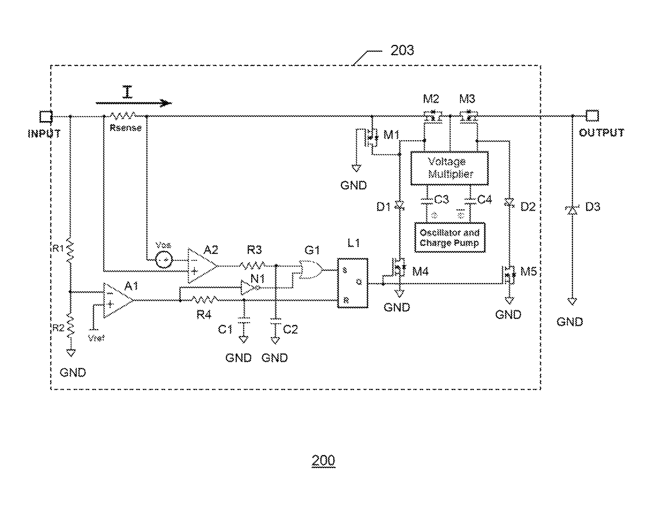
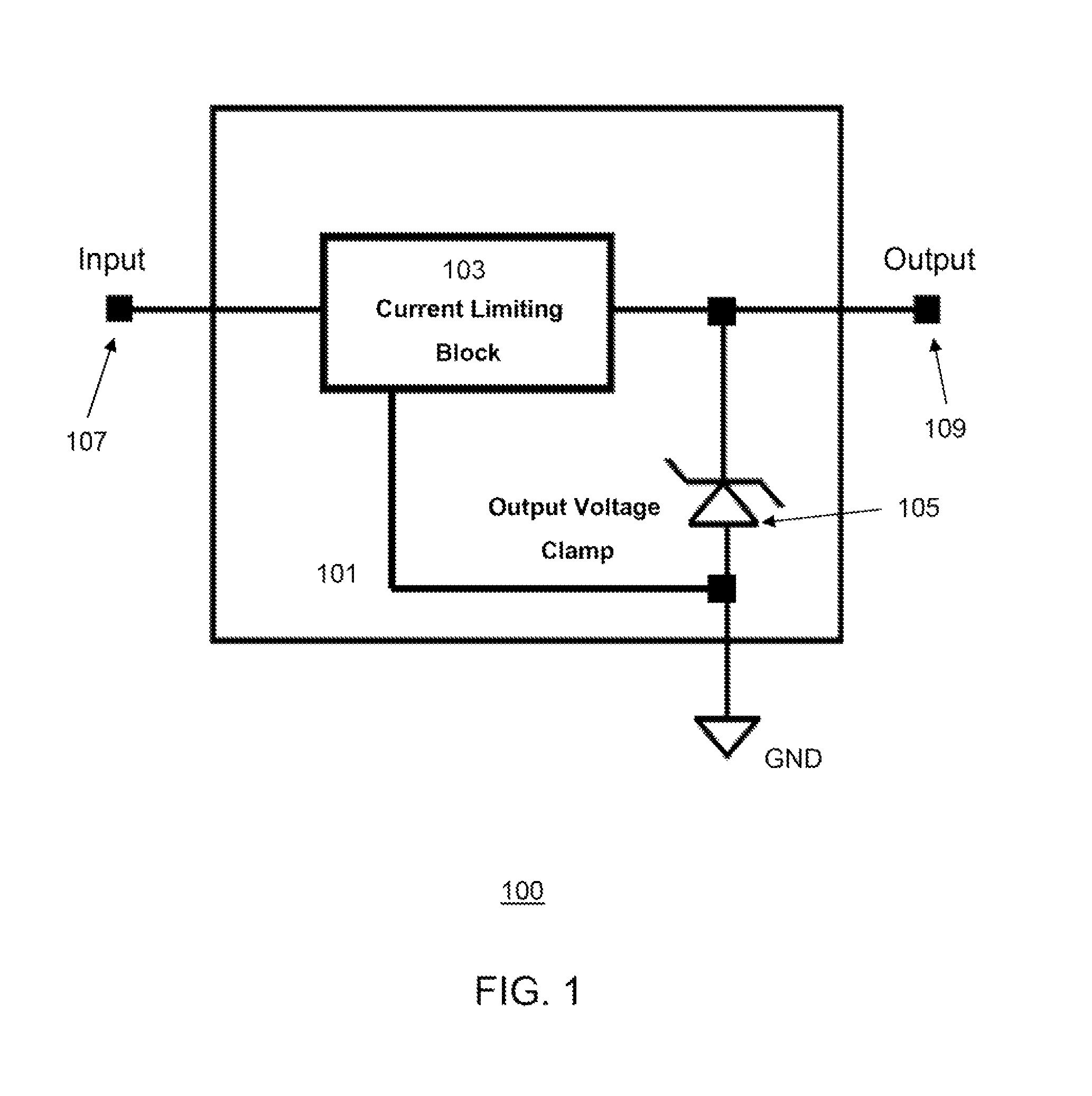
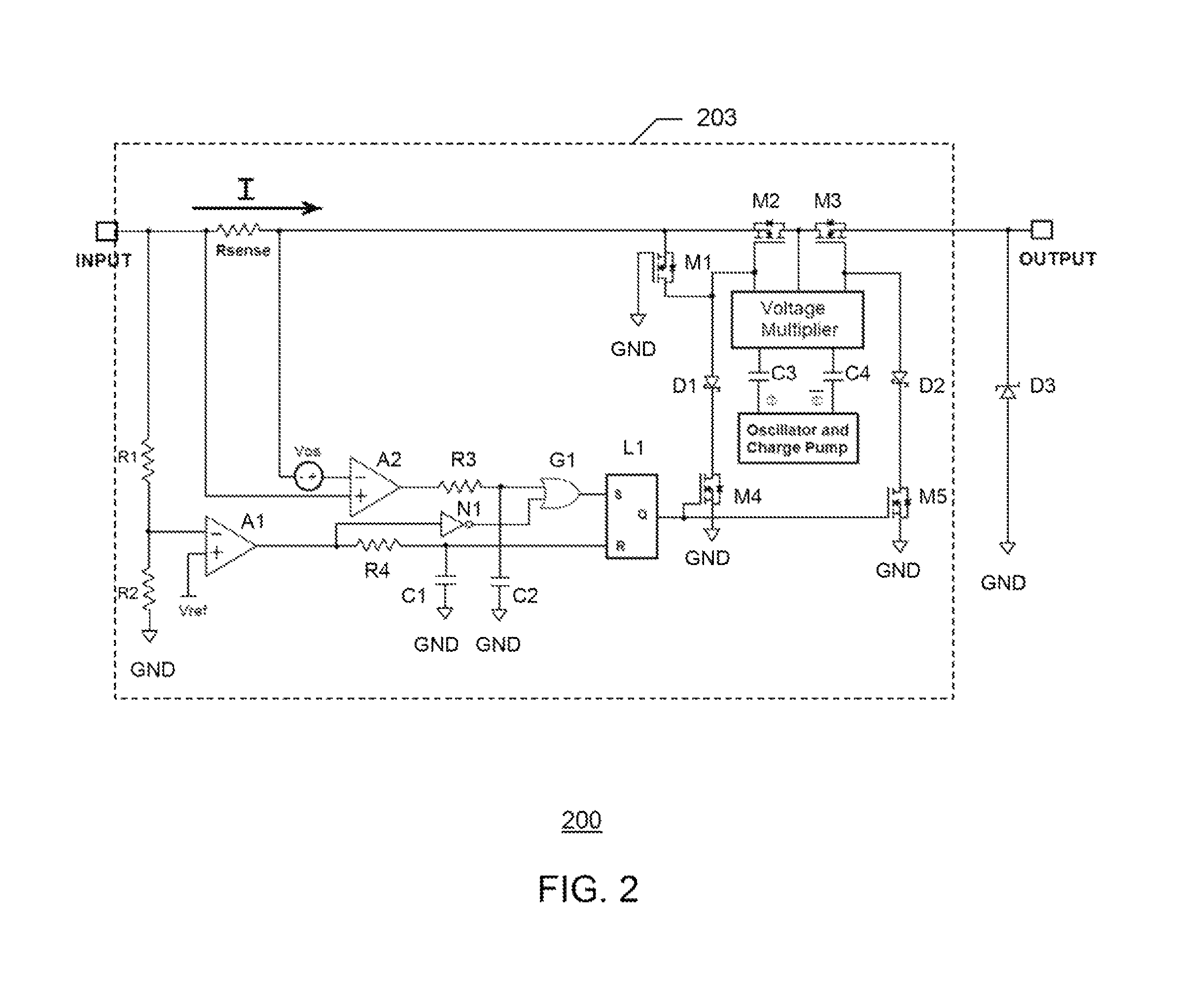
The present invention provides a method and system for protecting an electrical device from power surges using a monolithic semiconductor chip with a current limiting block and a voltage clamp. The chip includes at least one pair of common-drain series MOSFETs and at least one reverse polarity protection MOSFET to reduce or shut down the incoming electrical current as a current surge protection, and if the voltage coming out of the current limiting block is surging higher than a clamp output voltage of the output terminal, a second MOSFET holds down the voltage to the clamp output voltage as a voltage surge protection of the electrical device connected to the output terminal. The system includes an input terminal, an output terminal, the current limiting block, the output voltage clamp, and the monolithic semiconductor chip with the current limiting block and the output voltage clamp. The plurality of common-drain series MOSFETs and the additional MOSFET are dielectrically isolated from each other in the current limiting block to prevent substrate injection and latchup prevention in case of a reverse polarity voltage at the input terminal.

Problems solved by technology

Many electrical devices today operate in environments susceptible to unwanted and dangerous power surges or accidental reverse polarity input connections.
If power surges, which may involve a voltage surge, a current surge, or both, are sufficiently high or prolong beyond a negligible duration, electrical devices subject to power surges can sustain operation failure or permanent damages.
Therefore, while PPTC's are used in applications where slow power protection responses are acceptable, they are often undesirable in electronic circuits which require fast power protection responses and high energy efficiencies.
Earlier designs for transient blocking units (TBU's) were unable to perform a reset in case of a short-lived transient power surge event, thereby inconveniencing device users.
Furthermore, most TBU designs are generally incapable of protecting electrical circuits if a power surge event is sufficiently prolonged (i.e. non-transient).
In most of the conventional power protection system designs, including conventional fuses, relays, and TBU's, it is difficult to achieve a fast, stiff, and durable surge protection responses.
Because conventional power protection system designs tend to involve at least some discrete components such as a discrete package polymer-based device, a reduction or a shut-down of over-current and / or over-voltage event is often slower than desirable.
Furthermore, conventional power protections also typically suffer from fatigue and incremental degradation in protection performances over time.

Method used


Image

  • System and method for fast-acting power protection
  • System and method for fast-acting power protection
  • System and method for fast-acting power protection

Examples


Embodiment Construction

[0018]Specific embodiments of the invention will now be described in detail with reference to the accompanying figures. Like elements in the various figures are denoted by like reference numerals for consistency.

[0019]In the following detailed description of embodiments of the invention, numerous specific details are set forth in order to provide a more thorough understanding of the invention. However, it will be apparent to one of ordinary skill in the art that the invention may be practiced without these specific details. In other instances, well-known features have not been described in detail to avoid unnecessarily complicating the description.

[0020]The detailed description is presented largely in terms of description of shapes, configurations, and / or other symbolic representations that directly or indirectly resemble a novel power protection system for an electrical device and / or a related method of protecting an electrical device using the novel power protection system. These ...


PUM


Abstract

A fast-acting power protection system and a related method of power protection are disclosed. In one embodiment of the invention, the fast-acting power protection system includes a current limiting block capable of reducing or shutting down an unwanted current or voltage surge at an input terminal of the fast-acting power protection system. The fast-acting power protection system also integrates an output voltage clamp and the current limiting block in one piece of monolithic semiconductor material, wherein the output voltage clamp protects an electrical device connected to an output terminal of the fast-acting power protection system from an unwanted voltage surge by rapidly clamping an output voltage to a clamp voltage. Furthermore, the fast-acting power protection system also protects from a reverse polarity input voltage and dielectrically isolates a MOSFET for reverse polarity protection from other current-limiting MOSFET's inside the current limiting block.

Description

BACKGROUND OF THE INVENTION[0001]The present invention generally relates to power protection systems for electrical devices. More specifically, the invention relates to one or more embodiments of a novel fast-acting power protection system and a related method for protection of an electrical device against voltage / current surges or reverse polarity input connections.[0002]Many electrical devices today operate in environments susceptible to unwanted and dangerous power surges or accidental reverse polarity input connections. If power surges, which may involve a voltage surge, a current surge, or both, are sufficiently high or prolong beyond a negligible duration, electrical devices subject to power surges can sustain operation failure or permanent damages. Therefore, protection against power surges have been commonly addressed by conventional fuses with thermal or magnetic elements, which are designed to cut off incoming electrical power.[0003]One example of a conventional fuse is a ...

Claims


Application Information

Patent Timeline
IPC IPC(8): H02H3/08
CPCH02H9/025H02H9/041H02H11/002H02H3/08H02H3/20
Inventor BANAK, MICHAEL ALANSRINIVASAN, VALLANGIMAN VENKATARAMAN
Owner MFG NETWORKS INC MNI
Learn More