Collapsible bottle, method of manufacturing a blank for such bottle and beverage-filled bottle dispensing system

a bottle and blank technology, applied in the field of inflatable, portable containers, can solve the problems of high transportation costs of empty bottles, large physical volume, and high environmental impact of bottled beverage market using rigid or semi-rigid bottles, so as to reduce the cost of transportation and storage of water, facilitate collection and handling, and encourage recycling

Inactive Publication Date: 2013-09-24
RIEDL JOHN THOMAS
View PDF8 Cites 103 Cited by
  • Summary
  • Abstract
  • Description
  • Claims
  • Application Information

AI Technical Summary

Benefits of technology

[0027]The grid of intersecting stiffener structures, once inflated and adequately pressurised, increase the overall stiffness of the wall section in the plane of the wall where these are present, ie provide increased resistance against bending and buckling as compared to a wall embodiment where no additional joining locations are provided beyond the joining seams that frame the wall section. This feature makes the bottle overall more rigid as compared to one with out such grid of additional stiffening bonding seams.
[0054]In a further, alternative aspect of the present invention, the concept of providing an inflatable, rigidity enhancing exoskeleton is used in devising an insulated, inflatable box blank, rather than one which is bottle-shaped, which can be erected by inflation of the blank at a point of sale or required use. The contents of such ‘self-erecting’ boxes would typically be solids, although small quantities of fluids can be accommodated. Such self-erecting insulated boxes can be used to replace rigid and semi-rigid polyurethane foam boxes and similar containers of expanded materials used for conveying perishable goods that require temperature control during short-term storage or transport. Seafood is an example of such goods. As in the case of the bottle, such inflatable boxes can be supplied on a roll or in a cassette and are erected by inflation with air or gas supplied from a dispensing machine. The dispensing machine (and the inflatable blanks it contains) is relatively small and occupy a much smaller volume than the stock of conventional insulating boxes they replace. Such insulated, inflatable boxes are therefore of considerable benefit to the provider of the perishable goods in saving expensive floor space, often in retail situations. They are also of considerable benefit to the end user, in that they collapse for easy disposal, after use, to a very small volume compared with the polyurethane foam and similar expanded materials that they replace.

Problems solved by technology

However, transport costs of empty bottles are still high, as freight is also charged based on volume.
A further drawback that exists with existing beverage bottles is that whereas many of the conventional rigid and semi-rigid bottles used are recyclable, a great many are dumped and occupy large physical volumes in the collection, removal, transport, disposal and landfill processes.
The bottled beverage market using rigid or semi-rigid bottles is therefore environmentally highly negative, despite the ‘recyclable’ nature of the bottles.
Because of the nature of manufacture and filling of these type of liquid containers, large centralised filling (‘bottling’) stations are required, from where the filled cartons are then shipped to points of sale, again often over large distances and in bulky fashion.
However, beverage pouch filling operations are currently effected at larger filling facilities and the concomitant high transport and storage costs for the filled pouches to reach the point of consumption noted above in the context of rigid bottles still apply.
Furthermore, beverage-filled pouches have not found wide-spread consumer acceptance, possibly because of tactile misapprehensions in that the malleable nature of such pouches fosters ease of deformation during dispensing, which thus requires such pouches to be provided with a straw for dispensing its liquid contents into the mouth of a person.
Nonetheless, the malleable nature of the pouch remains a drawback for many users.
Because the bladder is flexible and mobile and hence very awkward to hold, without the external cardboard container, such bladders are impractical to use.
A particular problem arises in the context of providing an inflatable liquid container of the type having planar side walls, eg a quadrilateral or multi-faceted bottle, where individual side wall panes adjoin along a vertical welding seam that extends over a substantial portion of the height of the bottle.
When inflated, even small pressure exerted simultaneously at oppositely located vertical edges of the bottle would lead to distortion of the bottle, akin to the deformation which a square would undergo into a rhombus when oppositely directed forces are applied to the corners of the square.
From a cost point of view, it is well known that branded bottled water shipped internationally in individual bottles results in a product often more expensive per liter than petrol.
The many handling, storage and transport steps associated with such approach are costly and have a large carbon foot-print.
In the case of domestic bottled water, as opposed to imported bottled water, the number of handling and transport steps are reduced, but are still very significant in both cost and carbon footprint.
Whilst circular-tubular configurations of the peripheral wall are easily envisioned, problems arise in the process of manufacturing an inflatable blank where a single double-skinned blank is to be cut and subsequently folded into a bottle with a bottom and top wall, where bonding of flaps or portions of the blank is required to make-up the bottom in particular and provide a cylindrical peripheral wall.

Method used


Image

  • Collapsible bottle, method of manufacturing a blank for such bottle and beverage-filled bottle dispensing system
  • Collapsible bottle, method of manufacturing a blank for such bottle and beverage-filled bottle dispensing system
  • Collapsible bottle, method of manufacturing a blank for such bottle and beverage-filled bottle dispensing system

Examples


Embodiment Construction

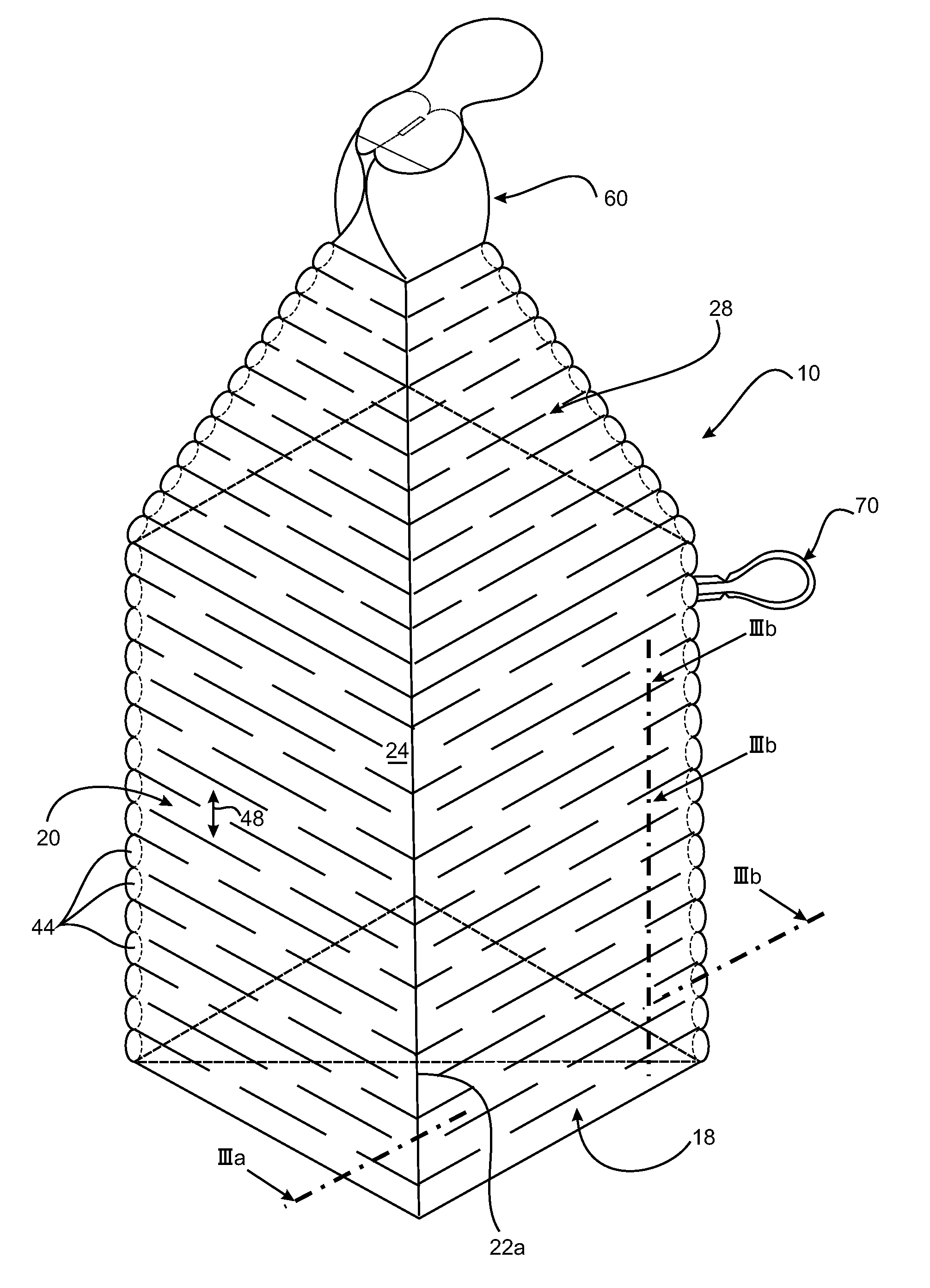
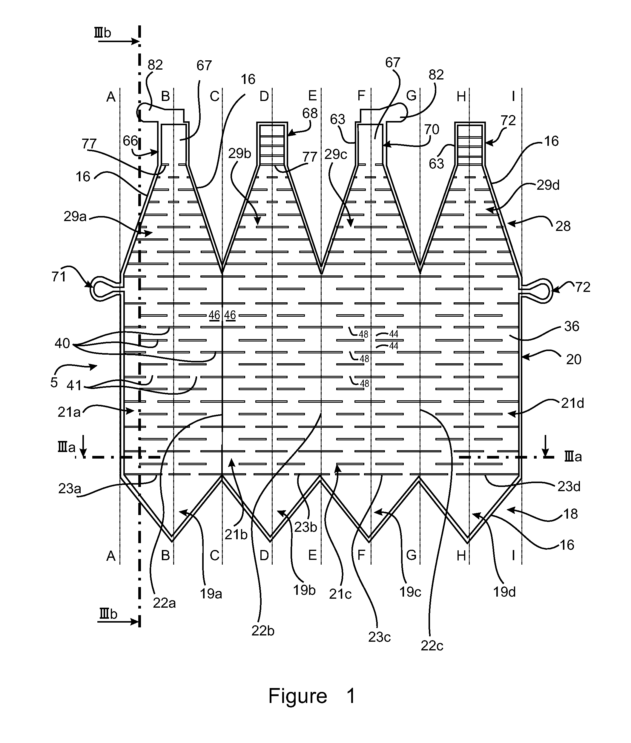
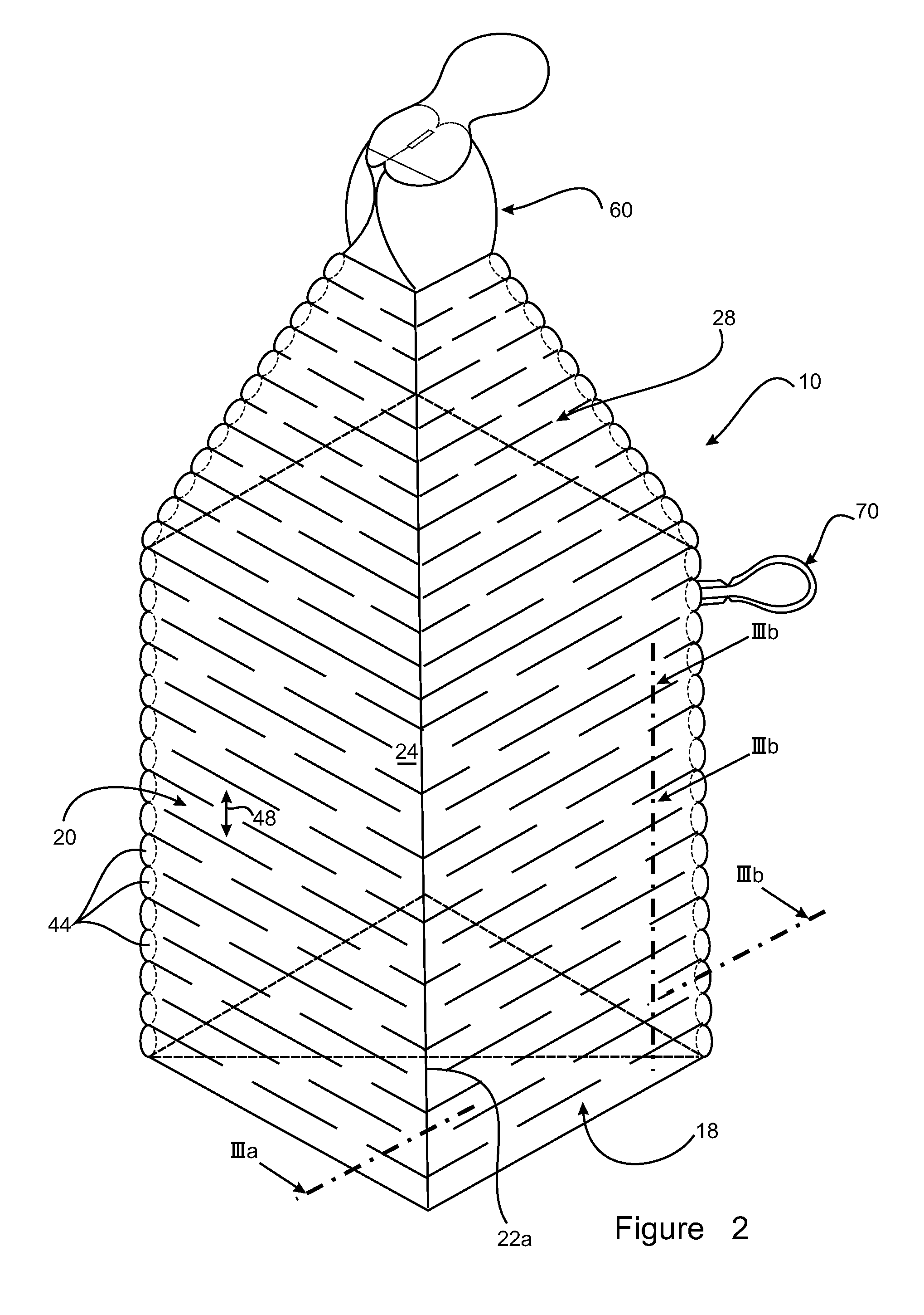
[0072]Turning first to FIGS. 1 and 2, FIG. 1 shows a plan view of a double-skinned blank 5 which after further folding and selectively edge-bonding at specific perimeter locations of the blank 5, as explained below, is transformed / shaped into an inflatable bottle blank which in turn can then be inflated into a deployed state as is schematically illustrated in the simplified isometric depiction of bottle 10 in FIG. 2. The different stages of manufacturing the blank 5 of FIG. 1, the folded and bonded bottle blank (not shown) and subsequent filling operations to inflate the collapsible double-skinned walls of the bottle 10 to make same a relatively shape stable and rigid bottle (as per FIG. 2) and to fill the bottle itself with a beverage (eg water), will be addressed in turn in the following description.

[0073]The bottle 10 in FIG. 2, shown in inflated state, is of polyhedral configuration, quadrilateral (eg square) in cross-section. It has a square bottom wall 18 (standing base of bot...


PUM

PropertyMeasurementUnit
filling volumesaaaaaaaaaa
pressuresaaaaaaaaaa
temperatureaaaaaaaaaa

Abstract

A double-skinned inflatable bottle blank is manufactured by: (i) stacking two sheets of liquid impermeable, flexible foil material; (ii) blanking the sheets; (iii) bonding the two blanks along joining seams that follow contoured perimeter edges to define a double skinned blank which can be inflated through an inflation location; (iv) additionally bonding the two blanks at in a predetermined grid of seams to provide an upstanding peripheral wall with intersecting, inflatable stiffener structures; (v) folding the double skinned blank; and (vi) selectively bonding together portions of the joined perimeter edge of the double skinned blank to define a double-skinned, inflatable bottle blank with an internal cavity surrounded by a bottom wall, peripheral wall and top wall with a dispensing orifice, the inflatable stiffener structures between the seams providing an exoskeleton about the internal cavity when inflated.

Description

[0001]This is a national phase under 35 U.S.C. §371 et seq. of Application No. PCT / AU2010 / 000774 filed Jun. 21, 2010. This application is also a continuation of Application No. PCT / AU2010 / 001071 filed Aug. 20, 2010. The text and full drawings of Application No. PCT / AU2010 / 001071 are incorporated by reference.FIELD OF THE INVENTION[0002]The present invention is concerned with inflatable, portable containers, in particular bottle-shaped, for holding liquids, having a double-skinned wall of flexible and collapsible nature defining an inner cavity for holding a liquid and at least one inflation chamber between the inner and outer skins disposed to receive a fluid and be pressurised thereby to erect and impart rigidity to the bottle, an inflation valve with the wall providing sealable access to the inflation chamber and a dispensing orifice in communication with the inner cavity providing access to fill the bottle and dispense liquid from it. The invention is also concerned with methods ...

Claims


Application Information

Patent Timeline
Patent Type & Authority Patents(United States)
IPC IPC(8): B65D90/02A47J41/00
CPCB29B11/06B29C65/087B31B3/00B65D11/04B29B11/14Y10T428/1393B29C53/04B29C53/40B29C65/18B29C66/0042B29C66/8122B29C66/81457B29C66/83413B29C66/843B29C2793/009B29L2022/02B29L2031/7158B29K2827/18B29C65/7894B29C66/4326B29C66/43B29C66/73921B29C66/71B29C66/72321B29C66/72341B29C66/72343B29C66/1122B29C49/071B29C2949/0715B29K2023/06B29K2023/0633B29K2023/065B65D7/22B65D21/08B65D37/00B65B43/00
Inventor RIEDL, JOHN THOMAS
Owner RIEDL JOHN THOMAS
Why Eureka
Try Eureka