
LED based lamp including reflective hood to reduce variation in illuminance

a technology of leds and hoods, which is applied in the direction of semiconductor devices for light sources, fixed installations, lighting and heating apparatus, etc., can solve the problems of reducing the uniformity of illuminance within the emission angle, and achieve the effect of reducing heat generated by leds and assisting in the dissipation of hea

Inactive Publication Date: 2013-09-24
INTEMATIX
View PDF16 Cites 4 Cited by
  • Summary
  • Abstract
  • Description
  • Claims
  • Application Information

AI Technical Summary

Benefits of technology

[0009]To enhance the uniformity of light emission intensity the lamp can further comprise a light diffuser, such as a light transmissive window with a surface texturing (e.g. micro surface patterning or topology) that is interposed between the array of LEDs and the hood. Alternatively, the diffuser can comprise a partially light transmissive window such as a light transmissive plastics material which incorporates light scattering particles distributed throughout its volume. In yet a further arrangement the light diffuser can comprise a lens structure such as a Fresnel lens that is configured to direct the light emission in a particular direction. In such an arrangement the lens structure is configured in conjunction with the hood such the lamp produces a more uniform illuminance.
[0011]To aid in dissipating heat generated by the LEDs the hood can be fabricated from a thermally conductive material that preferably has a thermal conductivity of at least 150 Wm−1K−1 and more preferably at least 200 Wm−1K−1. In such an arrangement the hood can comprise aluminum, an alloy of aluminum, a magnesium alloy, a metal loaded plastics material or a thermally conductive ceramic material such as aluminum silicon carbide (AlSiC). To further assist in the dissipation of heat from the lamp the hood is preferably in thermal communication with the body such that the hood can assist in radiating heat from the front of the lamp.

Problems solved by technology

However, as light emission from a lamp is confined within a selected emission angle this can result in a greater proportion of the light emission being concentrated on the axis thereby further reducing illuminance uniformity within the emission angle.

Method used


Image

  • LED based lamp including reflective hood to reduce variation in illuminance
  • LED based lamp including reflective hood to reduce variation in illuminance
  • LED based lamp including reflective hood to reduce variation in illuminance

Examples


Embodiment Construction

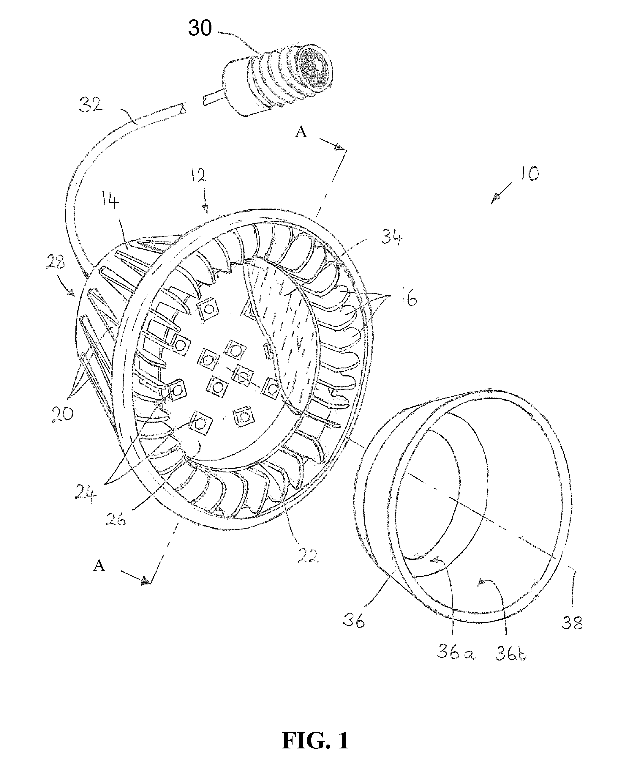
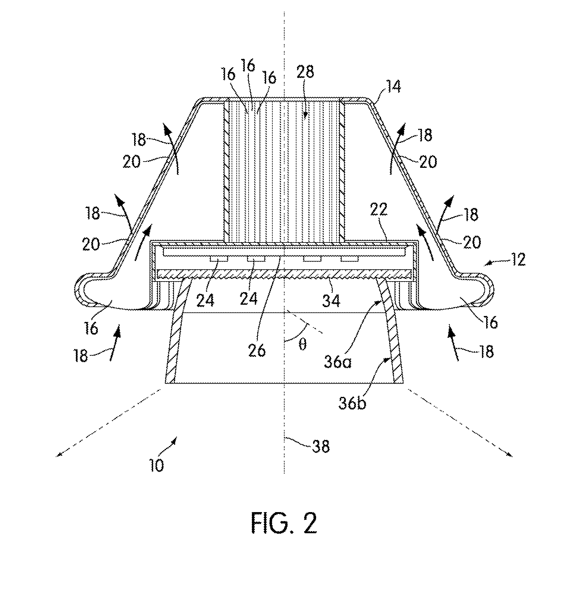
[0025]Embodiments of the invention are directed to LED based lamps comprising a light reflective hood located in front of a planar array of LEDs. The hood can comprise at least two substantially frustoconical (frustrum of a cone) light reflective surfaces that surround the array of LEDs and are configured such that in operation light emitted by the lamp is within a selected emission angle (beam spread) and has a variation in illuminance (luminous flux per unit area incident on a surface) below a selected value. Throughout this patent specification like reference numerals are used to denote like parts.

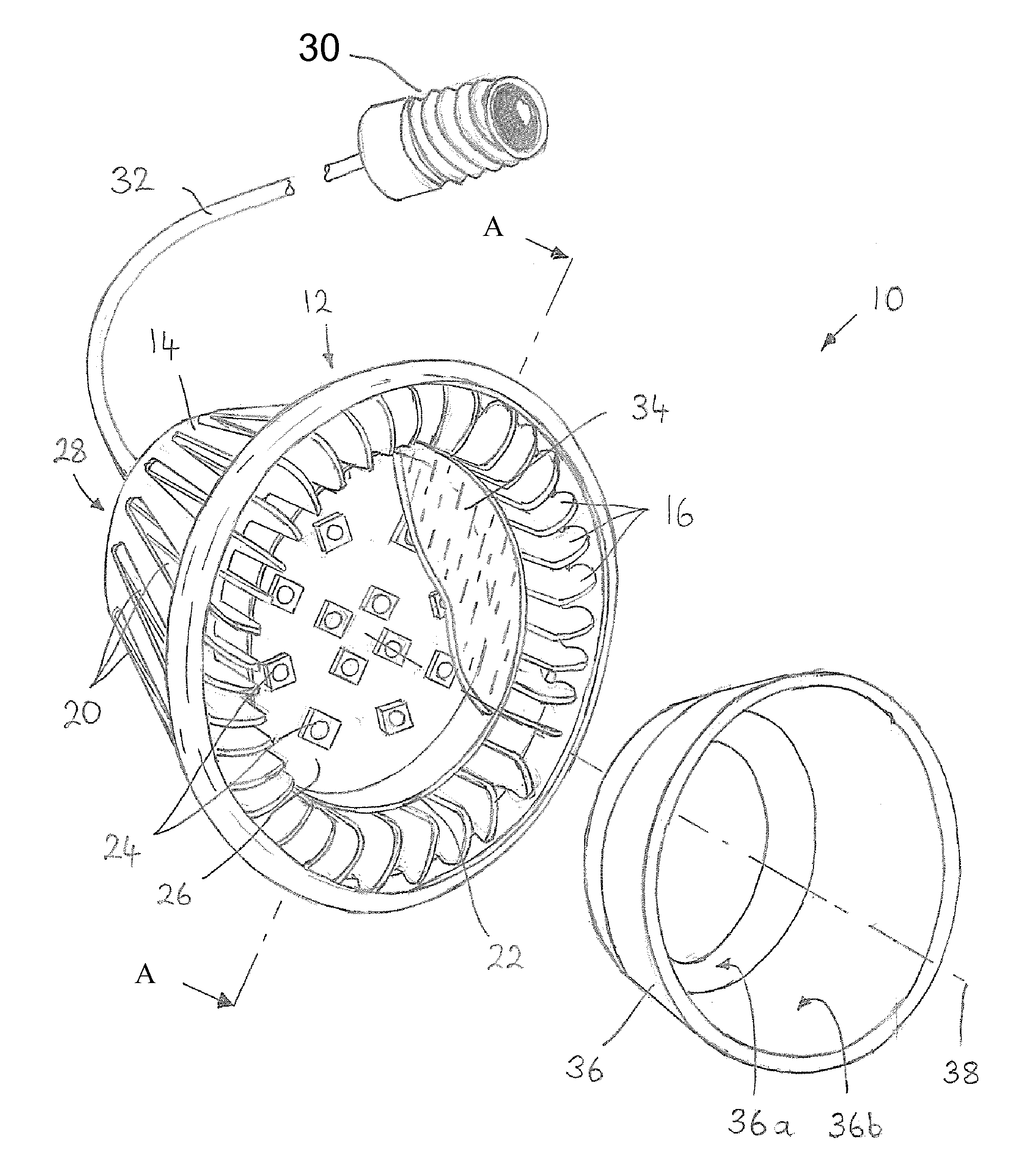
[0026]An LED lamp 10 in accordance with a first embodiment of the invention will now be described with reference to FIGS. 1 and 2 in which FIG. 1 is a partially exploded perspective view of the LED lamp and FIG. 2 is a schematic sectional view through A-A of FIG. 1. The LED lamp 10 is configured to generate white light with a Correlated Color Temperature (CCT) of ≈3000° K., an emission ...


PUM


Abstract

A lamp comprises: a thermally conductive body; a plurality of LEDs configured as an array and mounted in thermal communication with the body and a light reflective hood located in front of the plane of light emitting diodes. The hood has at least two frustoconical light reflective surfaces that surround the array of LEDs and are configured such that in operation light emitted by the lamp is within a selected emission angle (beam spread). The hood is configured such that in operation a variation in illuminance (luminous flux per unit area incident on a surface) is 10% or less over approximately a third to one half of the selected emission angle.

Description

CROSS-REFERENCE TO RELATED APPLICATIONS[0001]This application claims the benefit of U.S. Provisional Application No. 61 / 160,952, filed Mar. 17, 2009, the contents of which are incorporated herein by reference.BACKGROUND OF THE INVENTION[0002]1. Field of the Invention[0003]This invention relates to an LED (Light Emitting Diode) based lamp and in particular, although not exclusively, to such a lamp that can be used as a direct replacement for a filament (incandescent) lamp in a recessed lighting fixture such as a ceiling mountable downlight.[0004]2. Description of the Related Art[0005]White light emitting LEDs (“white LEDs”) are known in the art and are a relatively recent innovation. It was not until LEDs emitting in the blue / ultraviolet part of the electromagnetic spectrum were developed that it became practical to develop white light sources based on LEDs. As taught, for example in U.S. Pat. No. 5,998,925, white LEDs include one or more phosphor materials, that is photo-luminescent...

Claims


Application Information

Patent Timeline
Patent Type & Authority Patents(United States)
IPC IPC(8): H01J1/02H01J7/24H01J5/16
CPCF21K9/00F21S8/026F21V7/04F21V7/22F21V15/01F21V29/004F21V29/74F21V29/83F21S8/02F21V29/89F21V13/04F21Y2101/02F21Y2105/001F21V29/86F21V29/87F21V29/78F21Y2105/10F21Y2115/10F21V7/24
Inventor YANG, HAITAO
Owner INTEMATIX
Learn More