
Network topology discovery systems and methods

a network topology and network technology, applied in the field of data network topology discovery, can solve the problems of inability to provide performance diagnosis at the network level, and the estimation of end-to-end qos by only focusing on network utilization techniques

Active Publication Date: 2013-09-24
GULA CONSULTING LLC
View PDF148 Cites 44 Cited by
  • Summary
  • Abstract
  • Description
  • Claims
  • Application Information

AI Technical Summary

Benefits of technology

The invention is a tool that evaluates networks to determine if they are suitable for certain applications, specifically Voice over IP (VoIP). The tool uses a combination of techniques to measure the quality of service (QoS) and network utilization, allowing the diagnosis of QoS problems by identifying network devices that are causing issues. The tool also maps the entire topology of the network, which helps to better understand its capabilities. Overall, the invention provides a more effective way for network managers to design and implement VoIP features and services.

Problems solved by technology

Evaluation techniques based only on measuring the end-to-end QoS incurred by a target application treat the network as a black box and cannot provide performance diagnosis at the network level.
Similarly, techniques based only on measuring the network utilization cannot estimate the end-to-end QoS for the target application.

Method used


Image

  • Network topology discovery systems and methods
  • Network topology discovery systems and methods
  • Network topology discovery systems and methods

Examples


Embodiment Construction

[0080]The following detailed description and accompanying drawing figures depict illustrative embodiments of the present invention. Those skilled in the art will discern alternative system and method embodiments within the spirit of the present invention, and within the scope of the attached claims, from consideration of the present inventive teachings.

A. Notation

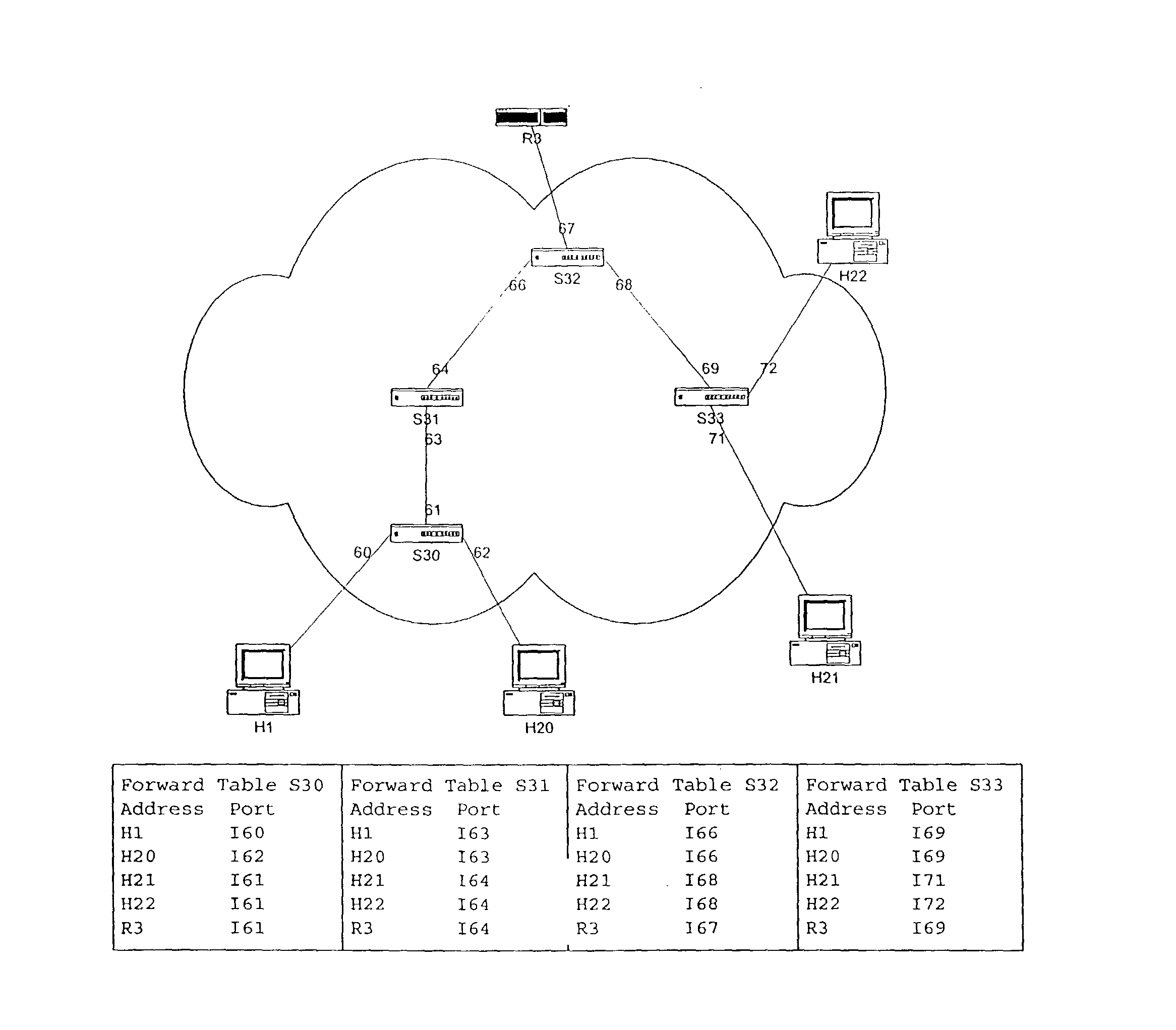
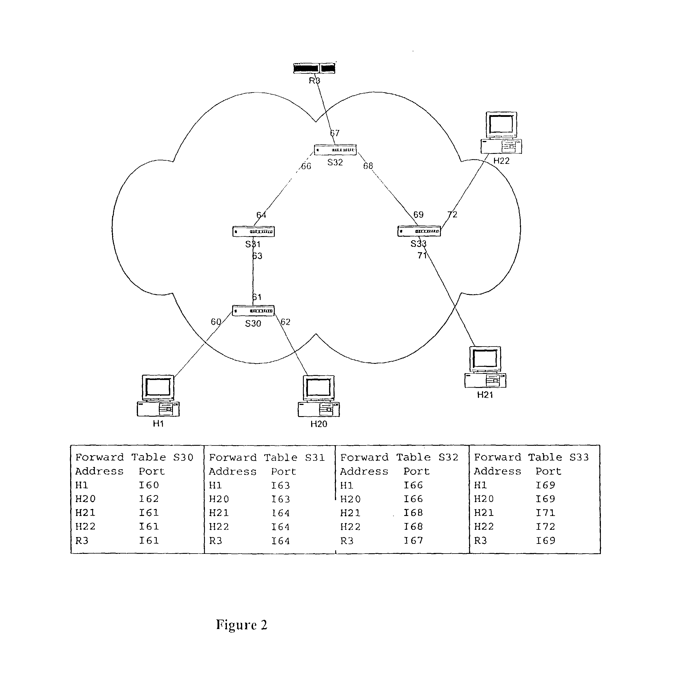
[0081]It proves convenient to represent an illustrative network topology using a graph G=(D, L), where the nodes of the graph, D, are a set of devices and the edges of the graph, L, are a set of links. A device of type router or switch is considered a switching device. Let Di and Dj be two devices in D where 1≦i,j≦|D|, i≠j. There is an edge between device Di and Dj if and only if there is a direct communications path between Di and Dj. Ii,j denotes the jth interface of device Di. Each edge out of a node (device) in the graph represents an interface in the network.

[0082]FIG. 3 illustrates the network devices involved in a sa...


PUM


Abstract

A system discovers the topology of devices in a network, such as all of the layer-2 and layer-3 devices, including routers and switches. The devices are mapped, as well as the links that join them. The devices are polled using SNMP requests. Route tables are derived from each router to determine addresses of the devices. A spanning tree process is used to discover layer-2 devices. Connections between layers are then discovered. Where information is incomplete, an undiscovered router cloud is recognized.

Description

RELATED APPLICATIONS[0001]The present application is related to concurrently filed non-provisional applications:[0002](i) Network Traffic Generation and Monitoring Systems and Methods and their Use in Testing Frameworks Determining Suitability of a Network for Target Applications; and[0003](ii) Report Generation and Visualization Systems and Methods and their Use in Testing Frameworks Determining Suitability of a Network for Target Applications, which concurrently filed applications are assigned to the assignee of the present application.[0004]The present application claims priority based on provisional application No. 60 / 329,569 filed Oct. 15, 2001.[0005]These related applications are hereby incorporated by reference in the present application as if set forth in their entirety herein.FIELD OF THE INVENTION[0006]The present invention relates to techniques for data network topology discovery, data network monitoring and analysis, and for reporting, display and visualization of such d...

Claims


Application Information

Patent Timeline
Patent Type & Authority Patents(United States)
IPC IPC(8): G06F15/173G06F15/16H04L12/24H04L12/26H04M3/22H04M7/00
CPCH04L41/0213H04L41/0663H04L41/12H04L41/22H04L41/5051H04L41/5087H04L41/509H04L43/0811H04L43/50H04M3/2236H04M3/2254H04M7/006H04L43/091
Inventor BEARDEN, MARK J.DENBY, LORRAINEKARACALI, BENGIMELOCHE, JEANSTOTT, DAVID THOMAS
Owner GULA CONSULTING LLC
Learn More