Handgun holster

a technology for handguns and holsters, applied in the field of handgun holsters, can solve the problems of increasing the time required to bring the firearm into action, and achieve the effect of improving the time required for carrying the firearm

Active Publication Date: 2013-10-01
LINEWEIGHT
View PDF13 Cites 45 Cited by
  • Summary
  • Abstract
  • Description
  • Claims
  • Application Information

AI Technical Summary

Benefits of technology

[0007]The handgun holster of the present invention permits sideward extraction of the weapon, and engages with the central portions of the handgun without regard to accessories mounted to the front or beneath the barrel. The holster has a nylon main element which engages the central region of the pistol in a snap fit between two opposed arms which project from the back wall of the main element and which are terminated by detents. Two lateral projections extend from the back wall to restrict the side-to-side displacement of the gun within the holster. Two resilient flaps extend from the main element and are connected to each other to extend around the engaged gun, providing additional retention, and covering the on / off switch of any flashlight accessory mounted to the gun. The main element is connected with an array of sector-shaped projections to a similar structure on a mounting assembly, to permit the main element to be set at any desired angular orientation with respect to the mounting assembly. The mounting assembly has two expandable parts with opposed flanges which permit mounting to either a conventional belt, or to a series of webbing pockets, such as in the military's PALS webbing attachment system.
[0008]It is a feature of the present invention to provide a pistol holster which allows a user to access the gun without having to draw the gun upward.
[0010]It is a further feature of the present invention to provide a pistol holster which provides a cover when not in use for the switch on a light mounted to the pistol, to restrict inadvertent activation of the light.
[0012]It is yet another feature of the present invention to provide a pistol holster which allows the pistol to be mounted at a desired rotational position.

Problems solved by technology

Moreover, vertical draw can be hampered by enclosed situations, and may increase the time required to bring the firearm into action.

Method used


Image

  • Handgun holster
  • Handgun holster
  • Handgun holster

Examples


Embodiment Construction

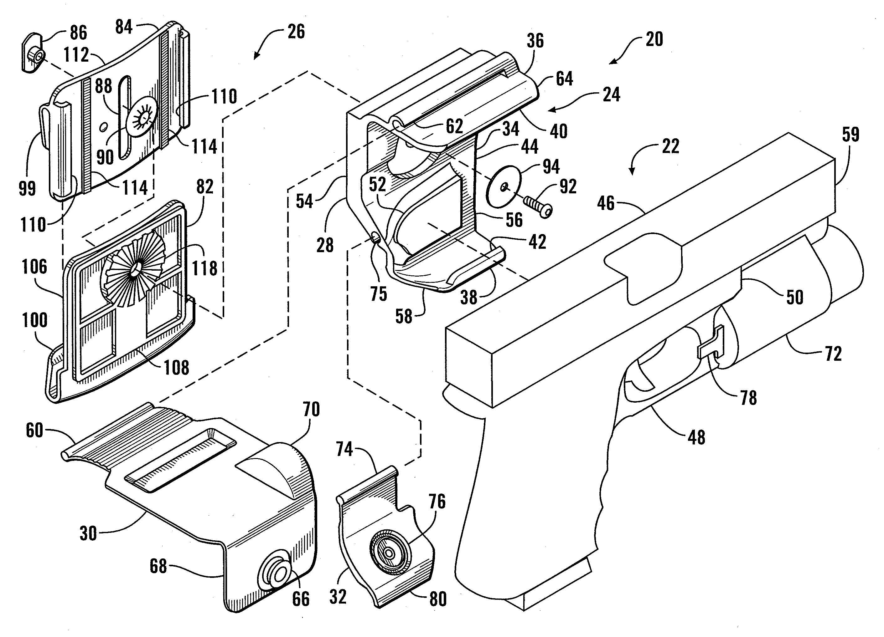
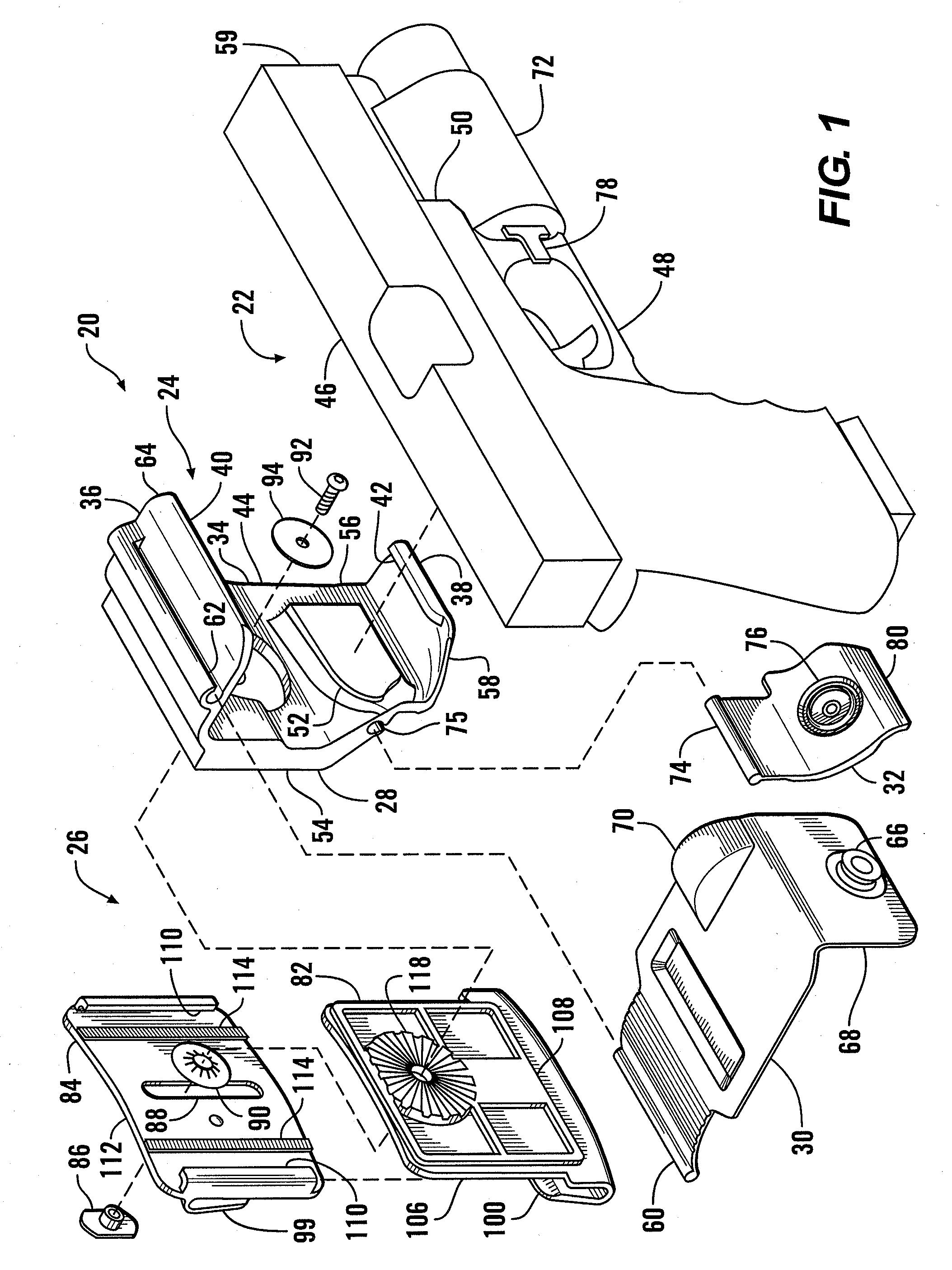
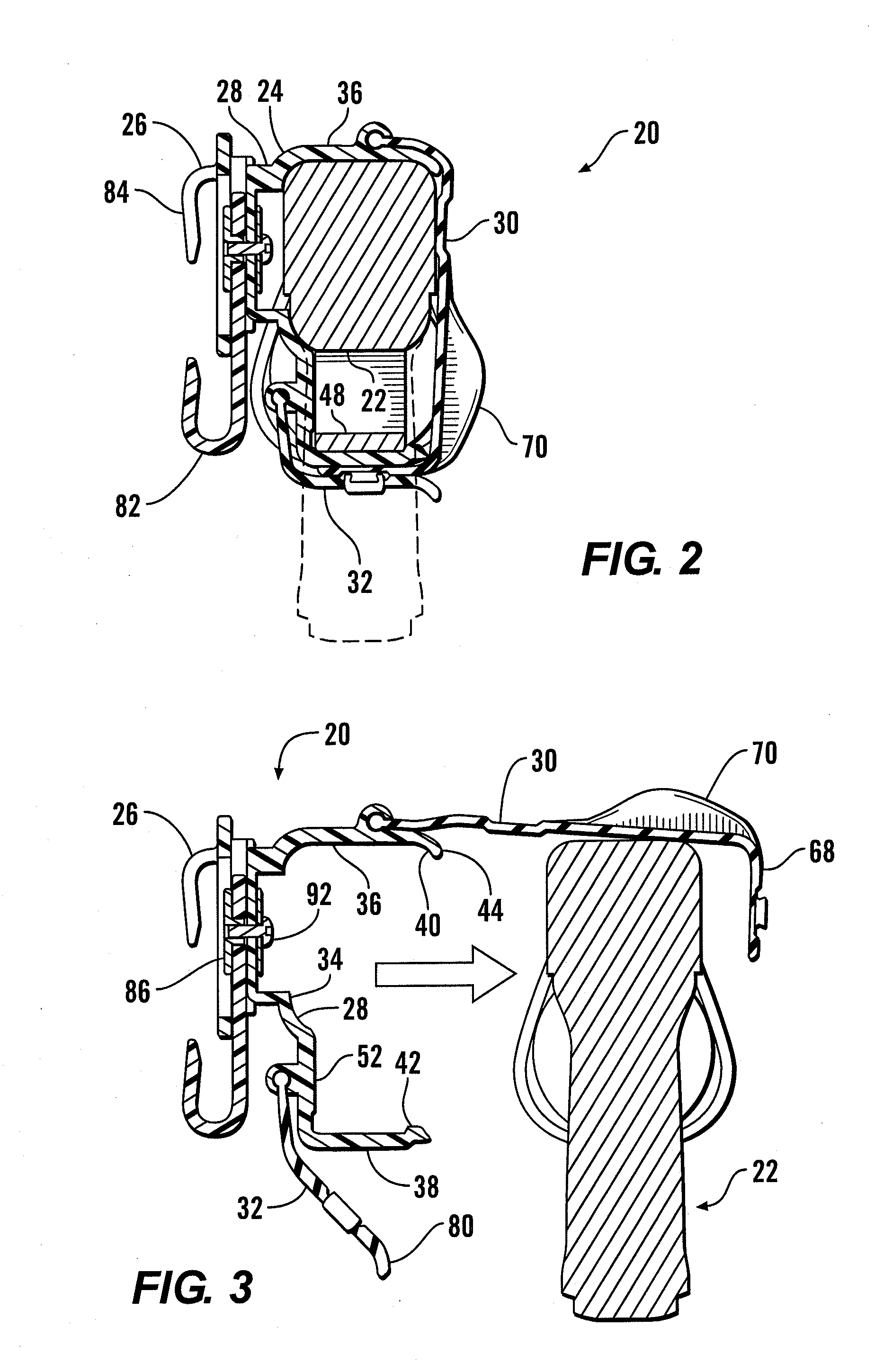
[0022]Referring more particularly to FIGS. 1-7, wherein like numbers refer to similar parts, a holster 20 for a pistol 22 is shown in FIGS. 1-4, and 6. The holster 20 is comprised of a retention assembly 24 which engages the pistol in a snap fit, and a mounting assembly 26 which is connected to the retention assembly at a selected orientation and which permits the holster to be mounted to a belt or a PALS webbing array.

[0023]The retention assembly is comprised of a plastic main element 28, best shown in FIGS. 1 and 6, to which a resilient main flap 30 and secondary flap 32 are mounted. The main element 28 is preferably formed of nylon, which is desirably resilient and lubricious, and which resists compression set and is less likely to be worn away by repetitive insertion and removal of the firearm. The main element is formed to be as stiff as possible without requiring an unacceptable amount of force to remove the gun. The stiffer the part, the more effectively it retains the gun.

[0...


PUM


Abstract

A handgun holster permits sideward extraction of the weapon, and engages with the central portions of the handgun without regard to accessories mounted to the front or beneath the barrel. The holster has a main element which engages the central region of the pistol in a snap fit between two opposed arms. Lateral projections extend from the back wall to restrict the side-to-side displacement of the gun and two resilient flaps extend around the engaged gun, providing additional retention, and covering the on / off switch of any flashlight accessory. The main element is connected to a mounting assembly to permit the main element to be set at any desired angular orientation with respect to the mounting assembly. The mounting assembly has two expandable parts with opposed flanges which permit mounting to either a conventional belt, or to a series of webbing pockets, such as in the military's PALS webbing attachment system.

Description

CROSS REFERENCES TO RELATED APPLICATIONS[0001]Not applicable.STATEMENT AS TO RIGHTS TO INVENTIONS MADE UNDER FEDERALLY SPONSORED RESEARCH AND DEVELOPMENT[0002]Not applicable.BACKGROUND OF THE INVENTION[0003]The present invention relates to devices for mounting a handgun to a user for ready access.[0004]The handgun is a weapon conventionally employed by public safety officers and military personnel in the line of duty. It is also carried by civilians for purposes of self-defense. In order to be readily available to project force when needed, the handgun must be supported on the user in a convenient and accessible fashion. A wide range of belt-mounted handgun holsters are known, as well as holsters supported by other rigs to facilitate concealed carry. A typical handgun holster may have a cup-like receptacle for the weapon. Such a holster requires the handgun to be withdrawn upwardly, requiring that the region above the holster be kept clear of other equipment or accessories. Moreover...

Claims


Application Information

Patent Timeline
Patent Type & Authority Patents(United States)
IPC IPC(8): F41C33/02
CPCF41C33/0236F41C33/045
Inventor CRYE, CALEB CLARK
Owner LINEWEIGHT
Why Eureka
Try Eureka