Reducer of electronic power steering apparatus

a technology of electronic power steering and reducing device, which is applied in the direction of gearing details, gearing, transportation and packaging, etc., can solve the problems of affecting the accuracy of auxiliary steering force transmission and rattle noise, and achieve the effect of reducing rattle noise, preventing clearance, and minimizing the change of clearan

Active Publication Date: 2013-10-08
HL MANDO CORP
View PDF16 Cites 19 Cited by
  • Summary
  • Abstract
  • Description
  • Claims
  • Application Information

AI Technical Summary

Benefits of technology

[0017]Accordingly, the present invention has been made to solve the above-mentioned problems occurring in the prior art, and an object of the present invention is to provide a reducer of an electronic power steering apparatus that aids the operation of a steering wheel by the driver by preventing a clearance from being caused by frictional wear between a worm and a worm wheel, by reducing rattle noise caused by backlash, and by minimizing the change in the clearance due to a change in torque.
[0019]The inventive reducer of an electronic power steering apparatus according to the present invention aids the accurate operation of a steering wheel by the driver by preventing a clearance from being caused by frictional wear between a worm and a worm wheel, by reducing rattle noise caused by backlash, and by minimizing the change in the clearance due to a change in torque.

Problems solved by technology

However, in the reducer of the conventional electronic power steering apparatus, a clearance is caused by frictional wear between the worm rotated by the drive force of the motor and the worm wheel and rattle noise is generated by backlash.
This problem, in turn, hampers accurate transmission of the auxiliary steering force for aiding the operation of the steering wheel by the driver.

Method used


Image

  • Reducer of electronic power steering apparatus
  • Reducer of electronic power steering apparatus
  • Reducer of electronic power steering apparatus

Examples


first embodiment

[0034]As illustrated in FIGS. 3 and 4, the reducer 300 of an electronic power steering apparatus 300 according to the present invention includes a worm shaft bearing 257 supporting an end of a worm shaft 254 on which a worm 152 enmeshing with a worm wheel 156 is formed, the end of the worm shaft 254 being opposite to a portion of the worm shaft 254 to which a motor shaft is coupled; a hollow bearing holder 310 mounted on an outer race 270 of the worm shaft bearing 257 such that a clearance is maintained between the bearing holder 310 and the outer race 270 of the worm shaft bearing 257; a holder housing 330 surrounding the outer periphery of the bearing holder 310 and fitted with an inner end of a gear housing 260; a worm shaft holder 320 coupled to an end of the worm shaft 254 such that a clearance 370 is formed between the worm shaft holder 320 and the inner surface of the holder housing 330 in the direction of the worm wheel 156; and a resilient support 340 coupled between the in...

third embodiment

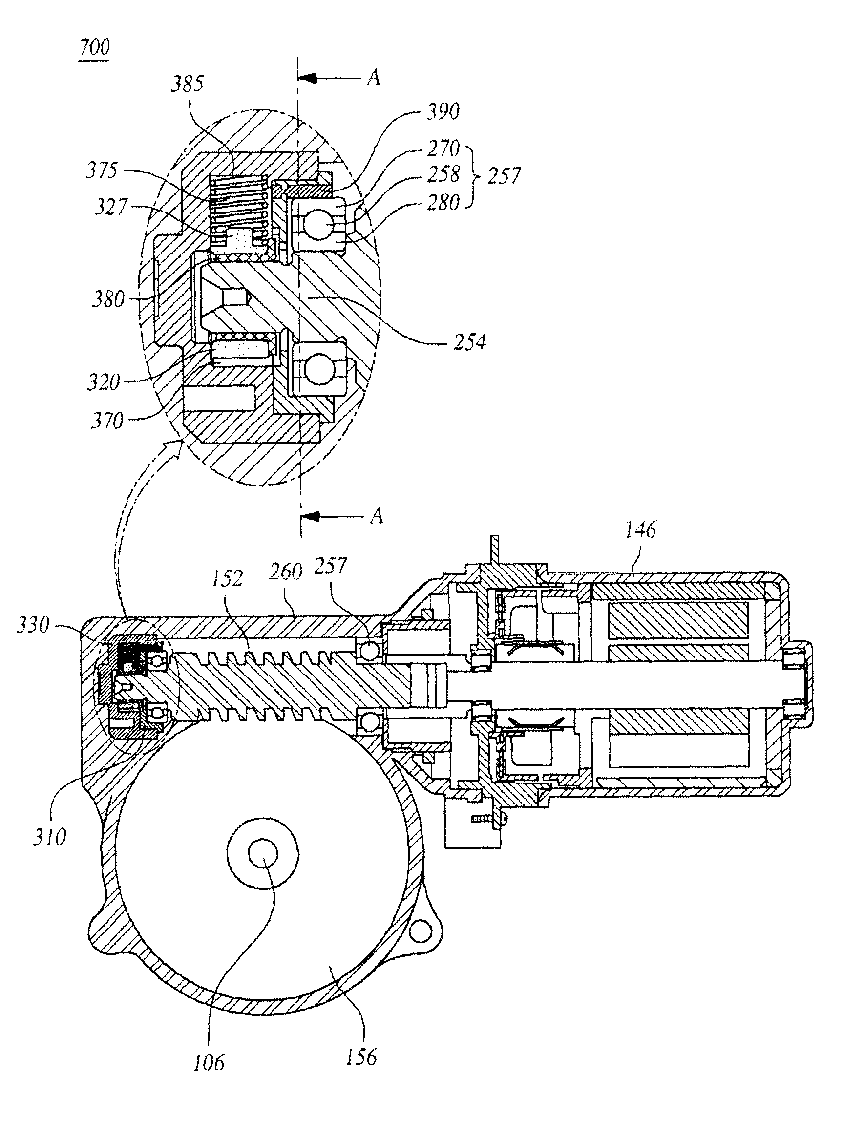
[0055]FIG. 7 is an exploded perspective view illustrating a portion of a reducer of an electronic power steering apparatus according to the present invention. FIG. 8 is a sectional view of the reducer of FIG. 7. FIG. 9 is a sectional view of a bearing holder taken along line A-A of FIG. 8.

[0056]As illustrated in FIGS. 7 to 9, the electronic power steering apparatus 700 according to the third embodiment of the present invention is the same as the first and second embodiments of the present invention except for a bush 380 provided between the worm shaft holder 320 and the worm shaft 254 and coated with PTFE (e.g., Teflon®) to reduce the rotational friction with the worm shaft 254, a worm shaft holder 320 having a protrusion 327, a bearing support 390, and a nonlinear coil spring 375, and a detailed description of the common structures will be omitted and the characteristics of the third embodiment of the present invention will be mainly described.

[0057]The bearing holder 310 is formed...


PUM


Abstract

A reducer of an electronic power steering apparatus is disclosed. The reducer of an electronic power steering apparatus aids the operation of a steering wheel by the driver by preventing a clearance from being caused by frictional wear between a worm and a worm wheel, by reducing rattle noise caused by backlash, and by minimizing the change in the clearance due to a change in torque.

Description

BACKGROUND OF THE INVENTION[0001]1. Field of the Invention[0002]The present invention relates to a reducer of an electronic power steering apparatus, and more particularly to a reducer of an electronic power steering apparatus that aids the operation of a steering wheel by the driver by preventing a clearance from being caused by frictional wear between a worm and a worm wheel, by reducing rattle noise caused by backlash, and by minimizing the change in the clearance due to a change in torque.[0003]2. Description of the Prior Art[0004]FIG. 1 is a schematic view of a conventional electronic power steering apparatus. As illustrated in FIG. 1, the electronic power steering apparatus 100 includes a steering system 130 extending from a steering wheel 102 to wheels 126 and an auxiliary power mechanism 140 providing auxiliary steering power to the steering system 130.[0005]The steering system 130 includes a steering shaft 106 one side of which is connected to the steering wheel 102 to be r...

Claims


Application Information

Patent Timeline
Patent Type & Authority Patents(United States)
IPC IPC(8): F16H35/00F16C23/00F16H1/16
CPCB62D5/0409F16H55/24F16H2057/0213Y10T74/19828
Inventor RHO, HEE-DONGJUNG, YOUNG-SOCK
Owner HL MANDO CORP
Why Eureka
Try Eureka