
Performing stuck-at testing using multiple isolation circuits

a technology of isolation circuits and stuck-at testing, which is applied in the field of integrated circuits, can solve the problems of reducing the performance of the circuit supplied by the supply voltage, reducing the amount by which the supply voltage may be reduced, and reducing the supply voltag

Inactive Publication Date: 2013-10-08
APPLE INC
View PDF27 Cites 6 Cited by
  • Summary
  • Abstract
  • Description
  • Claims
  • Application Information

AI Technical Summary

Problems solved by technology

However, there are limits to the amount by which the supply voltage may be reduced.
Reducing the supply voltage often reduces the performance of the circuits supplied by that supply voltage.
If the supply voltage from the source voltage domain of a level shifter is powered down, all input signals may be reduced to ground voltage, which may result in an inaccurate signal being provided to the receiving voltage domain by the level shifter.
Inaccurate operation can result.
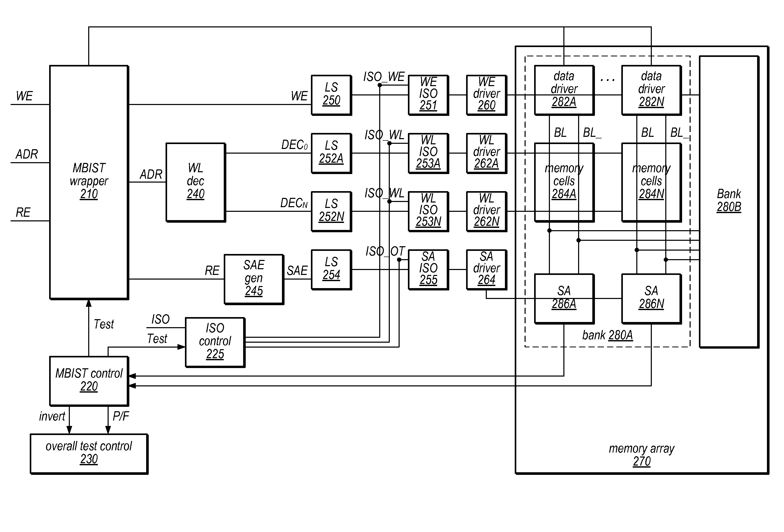
Accordingly, based on the results of these read and write operations, the testing circuit may determine stuck-at testing results for the memory.

Method used


Image

  • Performing stuck-at testing using multiple isolation circuits
  • Performing stuck-at testing using multiple isolation circuits
  • Performing stuck-at testing using multiple isolation circuits

Examples


Embodiment Construction

FIG. 1—Exemplary Integrated Circuit

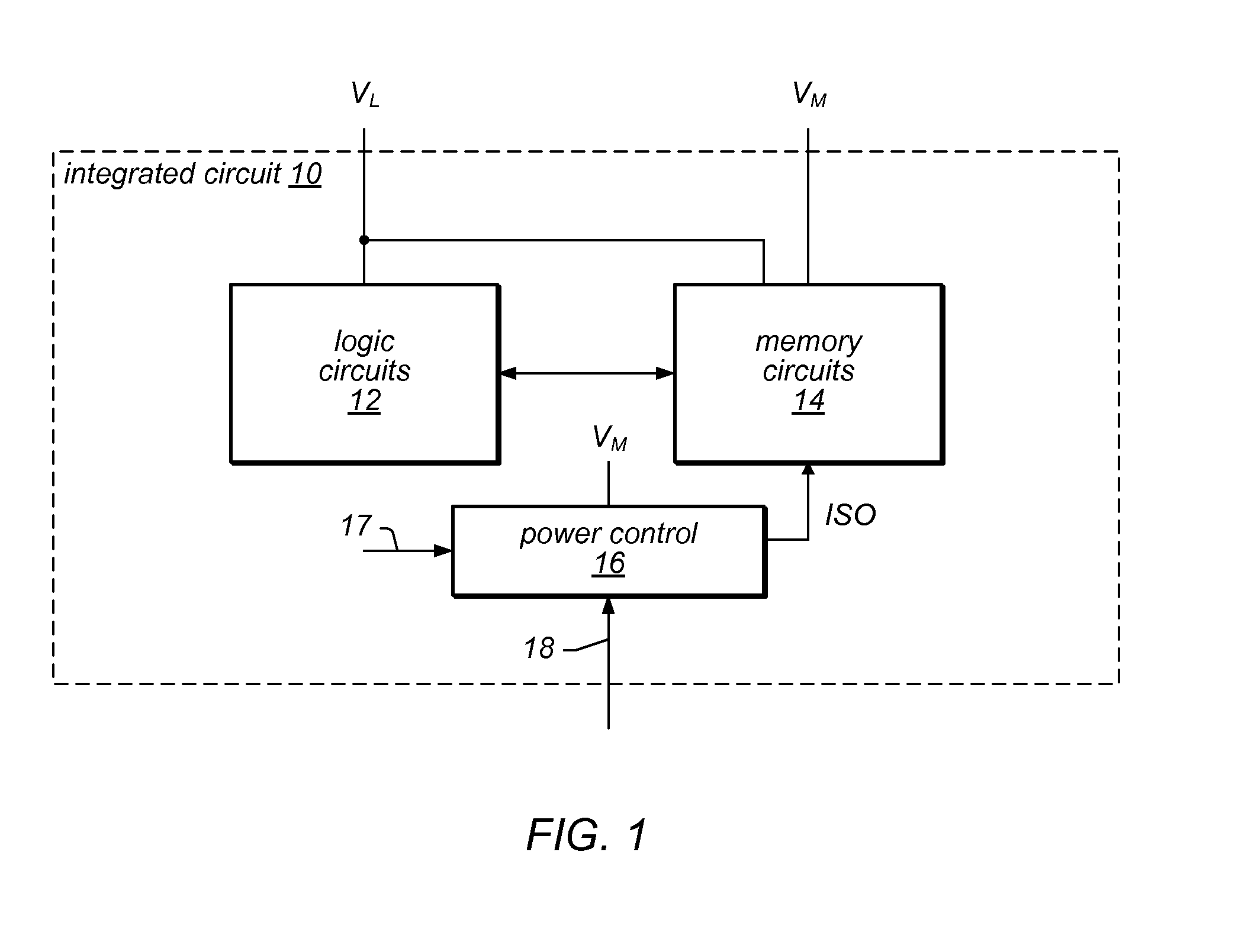
[0021]Turning now to FIG. 1, a block diagram of one embodiment of an integrated circuit 10 is shown. In the illustrated embodiment, the integrated circuit includes logic circuits 12, memory circuits 14, and a power control circuit 16. The logic circuits 12 are coupled to the memory circuits 14. The power control circuit 16 is coupled to the memory circuits 14 (specifically, via a ISO signal). The logic circuits 12 are powered by a first supply voltage provided to the integrated circuit 10 (labeled VL in FIG. 1). The memory circuits 14 and the power control circuit 16 are powered by a second power supply voltage provided to the integrated circuit 10 (labeled VM in FIG. 1). In the illustrated embodiment, the memory circuits 14 are also powered by the VL supply voltage, as will be explained in more detail for certain embodiments below. The integrated circuit 10 may generally comprise the logic circuits 12, the memory circuits 14, and the power control...


PUM


Abstract

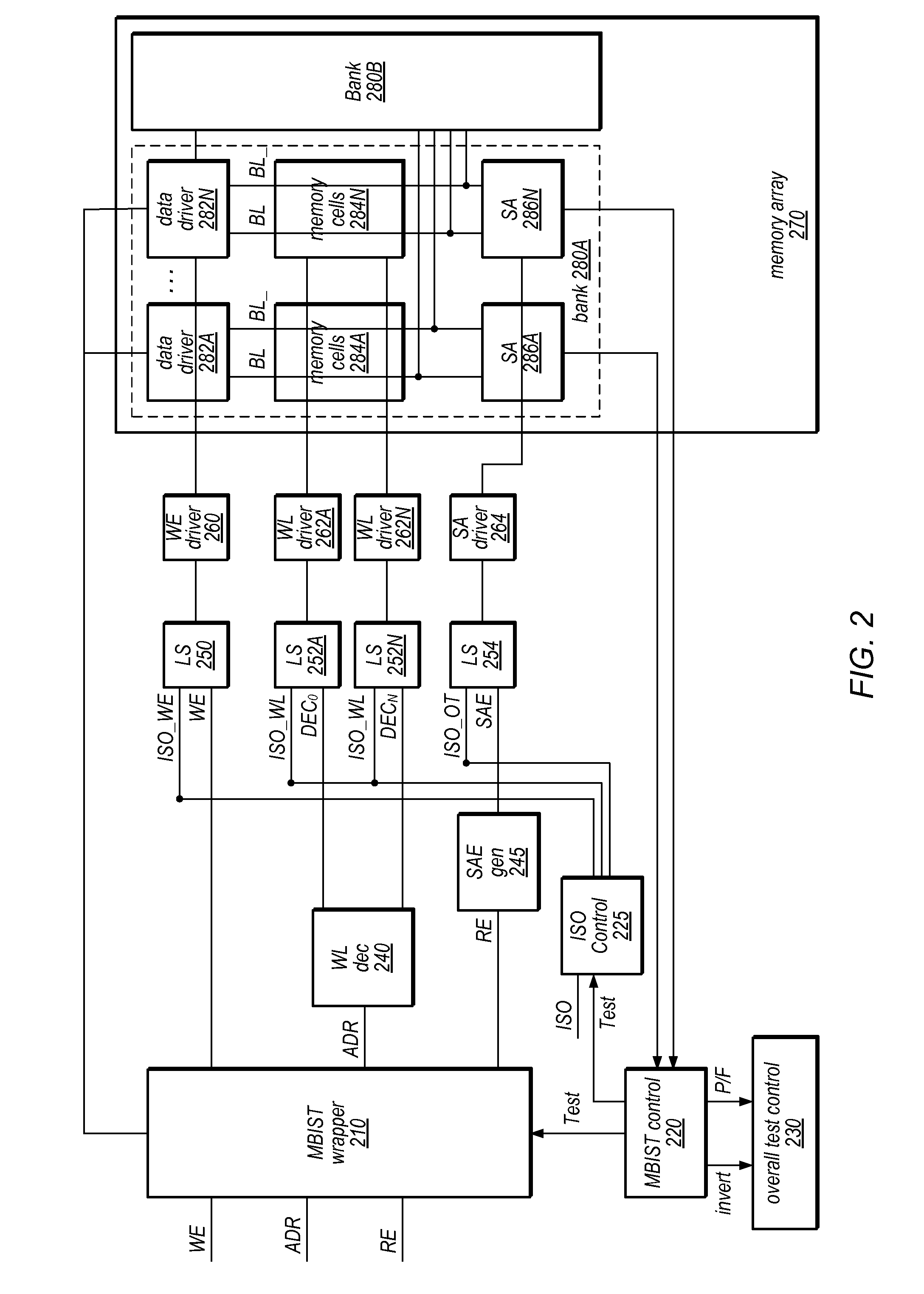
A memory may include a memory array, a plurality of control circuits, and a plurality of isolation circuits. The plurality of control circuits may be configured to generate control signals for the memory array. For example, the plurality of control circuits may include a plurality of word line driver circuits. The plurality of isolation circuits may be configured to receive the control signals from the plurality of control circuits and a plurality of isolation signals. A first isolation signal may correspond to the plurality of word line driver circuits and at least one second isolation signal may correspond to other ones of the plurality of control circuits. The first isolation signal and the second isolation signal may be independently controlled during memory tests to detect stuck-at faults associated with the plurality of isolation signals.

Description

BACKGROUND[0001]1. Field of the Invention[0002]This invention is related to the field of integrated circuits and, more particularly, to performing stuck-at testing of memories.[0003]2. Description of the Related Art[0004]For a variety of reasons, it is desirable to operate an integrated circuit at the lowest supply voltage possible while providing correct operation and the desired level of performance. However, there are limits to the amount by which the supply voltage may be reduced.[0005]Reducing the supply voltage often reduces the performance of the circuits supplied by that supply voltage. If some circuits in the integrated circuit are busy (and thus need to perform at or near peak operation), the supply voltage must generally remain at a relatively high level. Other, less busy circuits could operate at reduced voltages (or could even be powered off if idle). Additionally, in some cases, the logic circuitry can operate at a lower voltage than a corresponding on-chip memory can ...

Claims


Application Information

Patent Timeline
Patent Type & Authority Patents(United States)
IPC IPC(8): G11C5/14
CPCG11C8/08G11C29/04G11C29/30G11C2029/1202
Inventor CAMPBELL, BRIAN J.MURRAY, DANIEL C.ZIESLER, CONRAD H.
Owner APPLE INC
Learn More