
System and method for planning, disruption management, and optimization of networked, scheduled or on-demand air transport fleet trajectory operations

a fleet trajectory and air traffic technology, applied in the field of system and technology for controlling and monitoring air traffic within an airspace, can solve problems such as requiring continuous replanning, forcing others to re-plan, and ripple through the system, so as to reduce fuel burn, reduce fuel consumption, and maintain a population

Active Publication Date: 2013-10-08
SMARTSKY NETWORKS
View PDF7 Cites 25 Cited by
  • Summary
  • Abstract
  • Description
  • Claims
  • Application Information

AI Technical Summary

Benefits of technology

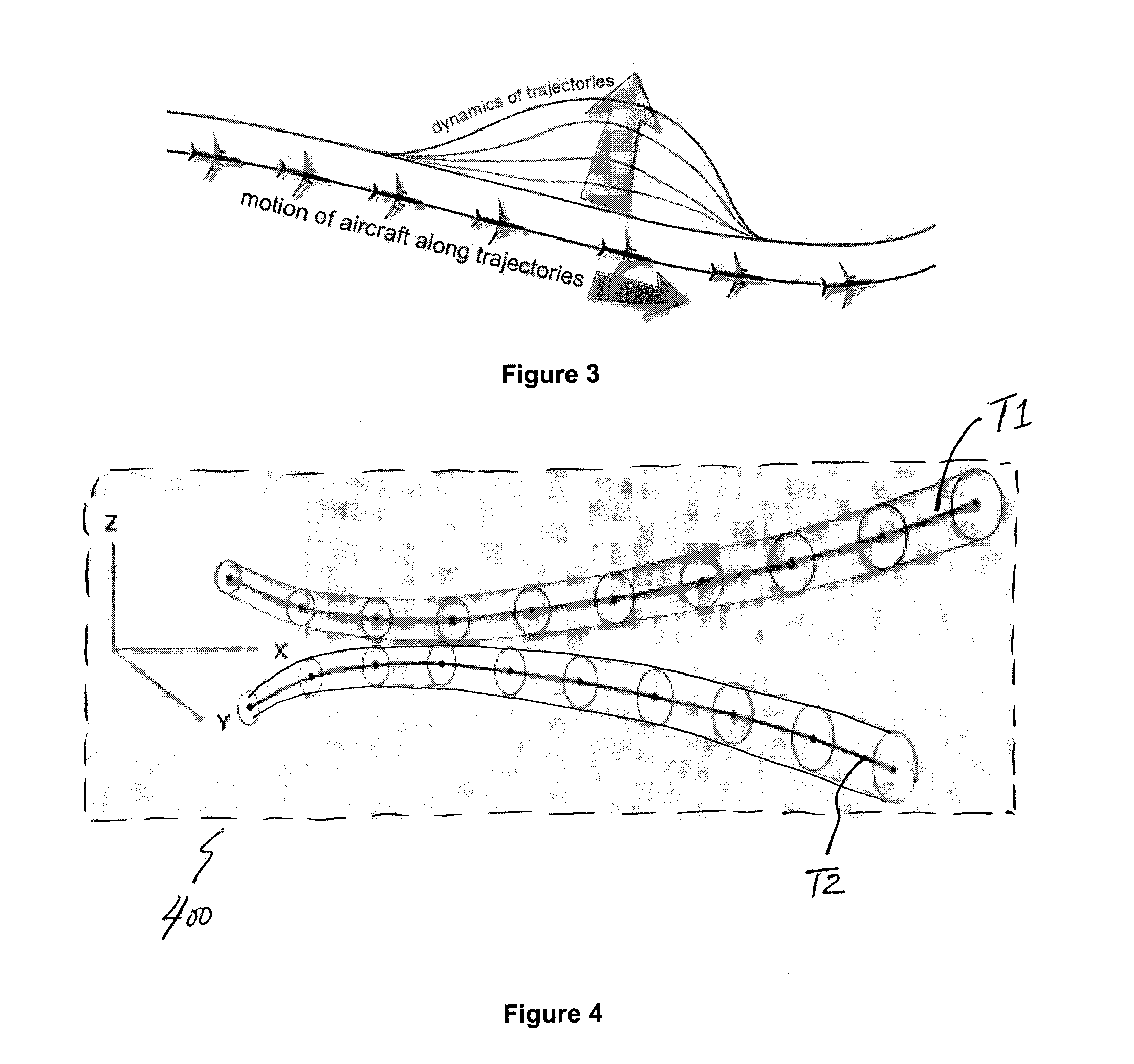
[0024]The system and technique disclosed herein utilize fully dynamical aircraft trajectories, and managing of the airspace in terms of its bulk properties. In the system and techniques disclosed herein, entire regions of airspace are characterized as solvable (or not)—within the limits of available computational resources—while accounting for the physical constraints of aircraft using the airspace, as well as short-lived constraints such as weather and airport closures. System and technique disclosed herein utilizes many “agents” representing aircraft trajectories that optimize their individual fitness functions in parallel. In addition, trajectory replanning comprises part of the dynamic trajectory management process. In this system and technique, the continual replanning of trajectories incorporates objective functions for the separation and maneuvering of the aircraft, the Air Navigation Service Provider (ANSP) business case considerations, as well as a pseudo-potential “charged string” concept for trajectory separation coupled with trajectory elasticity, together provide for the optimal management of airspace. The algorithms support monitoring of the collective dynamics of large numbers of heterogeneous aircraft (thousands to tens of thousands) in a national airspace undergoing continuous multidimensional and multi-objective trajectory replanning in the presence of obstructions and uncertainty, while optimizing performance measures and the conflicting trajectories.
[0026]Central to the focus of the computational modeling of trajectories is the concept of is continuously replanning the trajectories in the face of disruption. Dynamical Paths live in the context of many other DPs, also continuously replanning their trajectories. The disclosed system enables managing of a suite of trajectories to operate safely and efficaciously. Such approach not only applies to computation modeling and simulations but may be extended to and applied to actual flight in the airspace.
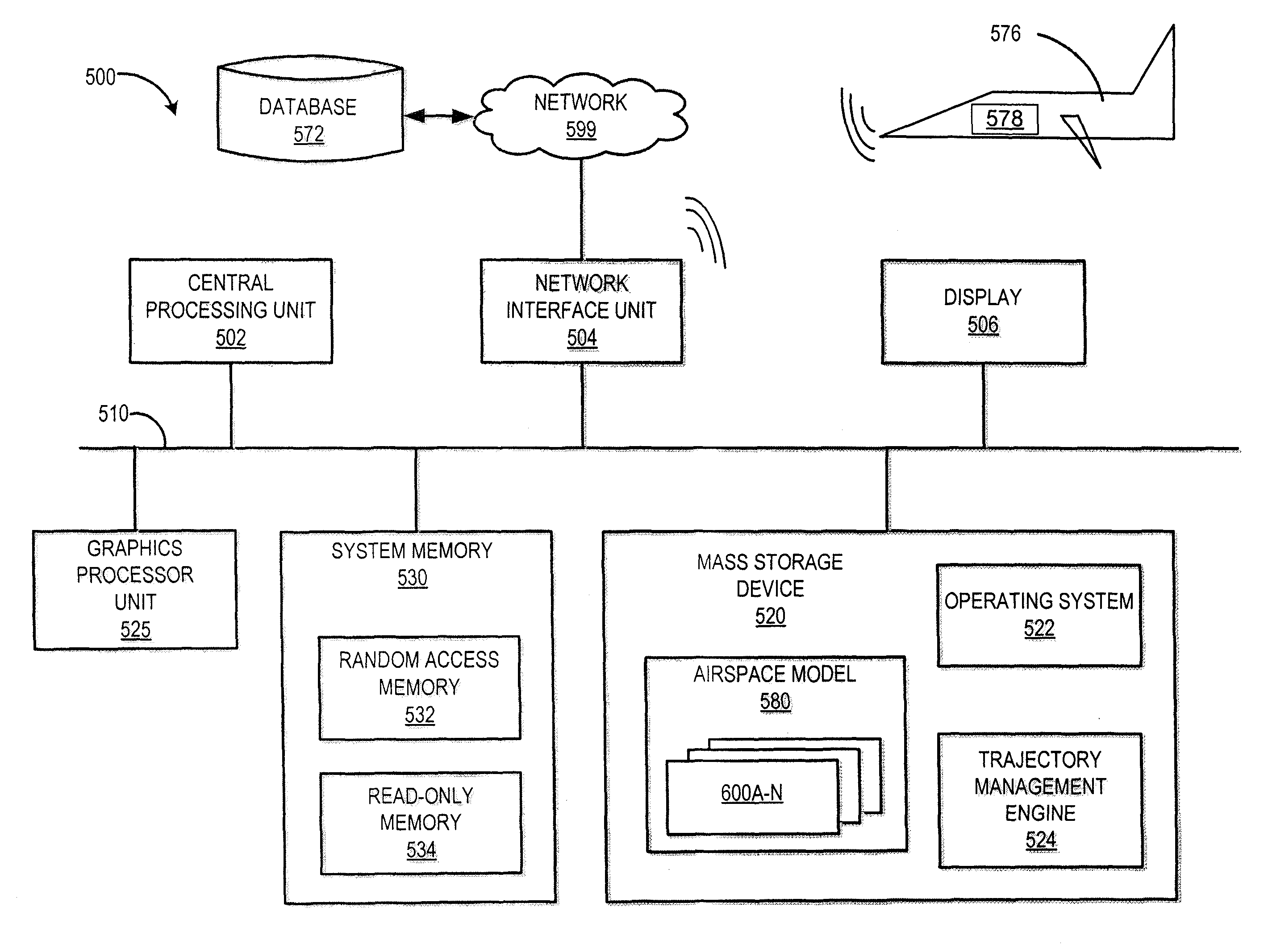
[0036]The computation is performed (organized) by software Agents. Conceptually, each Dynamical Path is endowed with “agency.” Agents are semi-autonomous software code objects acting on their own behalf. The unit of computation is the Dynamical Path, not the aircraft. It is the responsibility of each Agent to calculate a new Path plan at each DeltaT. Agents do their calculations based on available information. Agents do not negotiate per se, but do take into account information about other Paths. Agents use Cost Functions to evaluate Path options. Cost Functions quantify issues like separation, fuel consumption, and punctuality. Optimization is achieved by minimizing overall “costs” associated with a Path. Information Technology issues are not addressed per se by this Dynamical Path system. There are pros and cons with where to locate computational resources. Computing on board the aircraft reduces latency for replanning, etc., but can increase weight, cost, and other operational considerations. Centralizing computing on the ground, or distributing computing to the aircraft has its own set of tradeoffs. How and where to distribute computing is an ongoing research topic, but not addressed herein.
[0044]A population of Path Candidates is generated and evaluated. This technique is reminiscent of genetic algorithms (GAs), but computed in the continuous domain in the disclosed method. Many candidate Paths can be considered at once, simultaneously. This approach enables efficiently exploring the space of many possible Paths. The Graphical Processor Unit (GPU) technology (see below) is particularly efficient at maintaining a population of many Paths.
[0045]According to one aspect of the disclosure, a method for determining the capacity of airspace to safely handle multiple aircraft comprises: method for managing the flight performance parameters of a plurality of aircraft within an airspace comprises: A) upon entry of aircraft into an airspace, acquiring data describing a trajectory for each of the plurality of aircraft; B) periodically re-calculating each trajectory; C) identifying conflicts between pairs of trajectories or a trajectory and an obstacle within the airspace; and D) modifying at least one trajectory of the conflicting pair of trajectories or a trajectory in conflict with an obstacle within the airspace; wherein one of B) and D) are performed in accordance with at least one predetermined rule. In one embodiment, the at least one predetermined rule is selected from any of routing, altitude, speed, reduced fuel burn, reduced flight time, reduced emissions through shorter segments flown at optimum altitudes, seamless climb to cruise, optimal profile descents, customer-required destination time-of-arrival, minimized time-of-flight. In another embodiment, the at least one predetermined rule is selected from any of aircraft separation minimum and obstacle separation minimum.

Problems solved by technology

In systems with many elements, disruptions are endemic; hence, continuous replanning is required.
Even the best plan is only best in the context of other plans—hence, what is “best” can change dynamically and such change can ripple through the system, forcing others to re-plan as well.

Method used


Image

  • System and method for planning, disruption management, and optimization of networked, scheduled or on-demand air transport fleet trajectory operations
  • System and method for planning, disruption management, and optimization of networked, scheduled or on-demand air transport fleet trajectory operations
  • System and method for planning, disruption management, and optimization of networked, scheduled or on-demand air transport fleet trajectory operations

Examples


Embodiment Construction

[0070]

LIST OF ABBREVIATIONS AND ACRONYMS3SATThe Satisfiability Construct for all NP-hard problems4DTFour Dimensional Trajectories5DTFive Dimensional TrajectoriesABMAgent-Based ModelingANSPAir Navigation Service ProviderAOCAirline Operations CenterATMAir Traffic ManagementATOPAdvanced Technologies & Oceanic Procedures (FAA Ocean 21 Prog.)ATSPAir Transportation Service ProviderCUDACompute Unified Device ArchitectureDARPDynamic Airspace Reroute ProgramDCITData Communications Implementation Team (FAA)FANSFuture Air Navigation SystemFMCFlight Management ComputerJPDOJoint Planning and Development OfficeNextGenNext Generation Air Transportation SystemNASNational Airspace SystemPBCPerformance-Based CommunicationPBNPerformance-Based NavigationPBSPerformance-Based SurveillanceRBTReference Business TrajectoryRNPRequired Navigation PerformanceRTPRequired Time PerformanceRVSMReduced Vertical Separation MinimumsSAASense and AvoidSESARSingle European Sky Advanced ResearchTBOTrajectory-Based Operat...


PUM


Abstract

Disclosed are algorithms and agent-based structures for a system and technique for analyzing and managing the airspace. The technique includes managing bulk properties of large numbers of heterogeneous multidimensional aircraft trajectories in an airspace, for the purpose of maintaining or increasing system safety, and to identify possible phase transition structures to predict when an airspace will approach the limits of its capacity. The paths of the multidimensional aircraft trajectories are continuously recalculated in the presence of changing conditions (traffic, exclusionary airspace, weather, for example) while optimizing performance measures and performing trajectory conflict detection and resolution. Such trajectories are represented as extended objects endowed with pseudo-potential, maintaining objectives for time, acceleration limits, and fuel-efficient paths by bending just enough to accommodate separation.

Description

RELATED APPLICATIONS[0001]This application claims priority to the following U.S. Patent Applications, the subject matters of which are incorporated herein by this reference for all purposes, including the following:[0002]U.S. Provisional Patent Application Ser. No. 61 / 435,999, filed on Jan. 25, 2011, entitled Airspace Phase Transitions And The Traffic Physics Of Interacting 4DTrajectories; and[0003]U.S. Provisional Patent Application Ser. No. 61 / 450,453, filed on Mar. 8, 2011, entitled Airspace Phase Transitions And The Traffic Physics Of Interacting 4DTrajectories.[0004]In addition, the subject matter of the following commonly owned U.S. Patent Applications, filed on even date herewith, is incorporated herein by this reference for all purposes:[0005]U.S. patent application Ser. No. 13 / 358,246, entitled Method And Apparatus For Dynamic Aircraft Trajectory Management.FIELD OF THE DISCLOSURE[0006]The disclosure relates traffic control and monitoring, and, more specifically, to systems...

Claims


Application Information

Patent Timeline
Patent Type & Authority Patents(United States)
IPC IPC(8): G06F19/00
CPCG08G5/0013G08G5/0052G08G5/0039G08G5/045G08G5/0043G08G5/0082G08G5/0017
Inventor SAWHILL, BRUCE K.HERRIOT, JAMES W.HOLMES, BRUCE J.
Owner SMARTSKY NETWORKS
Learn More