
Steel stud clip

a technology of studs and clips, applied in the direction of walls, constructions, building reinforcements, etc., can solve the problems of gaps, damage to surrounding foundations, interior structures such as floors, and exterior walls to go out of plumb, so as to reduce unnecessary friction and maximize connection strength

Active Publication Date: 2013-10-15
SIMPSON STRONG TIE
View PDF106 Cites 65 Cited by
  • Summary
  • Abstract
  • Description
  • Claims
  • Application Information

AI Technical Summary

Benefits of technology

The solution achieves substantial savings in material and cost by using lighter-gauge materials, reducing unnecessary friction, and optimizing load distribution, thereby enhancing the structural integrity and efficiency of the connectors.

Problems solved by technology

Buildings often settle on their foundations once constructed, which can cause exterior walls to go out of plumb, in turn causing damage to the surrounding foundation and to interior structures such as floors.
With exposure to extremes of temperature, gaps can be produced in the exterior sheathing panels if they expand or contract more than the framing, allowing cold air and moisture to intrude.
And curtain walls (e.g., partition walls) are not designed to support vertical loads and must therefore by isolated from deflection of the primary load-bearing support structure of the building due to changes in live or dead loads carried by that structure.
A variety of slide, or slip, clips that permit relative movement between structural members have been made, but none have successfully optimized the use of material in the clips and the loads achieved by the clips.

Method used


Image

  • Steel stud clip
  • Steel stud clip
  • Steel stud clip

Examples


Embodiment Construction

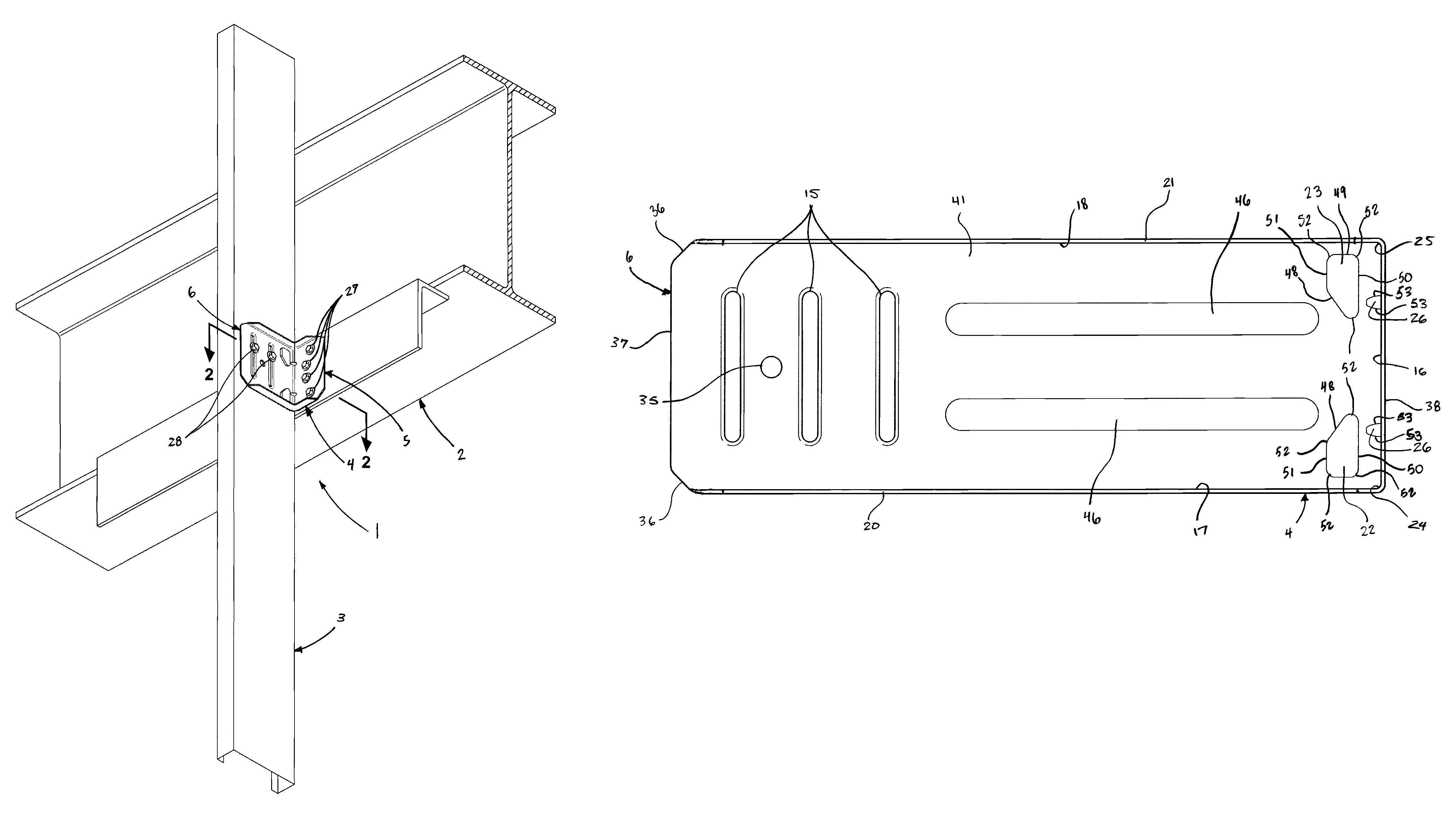
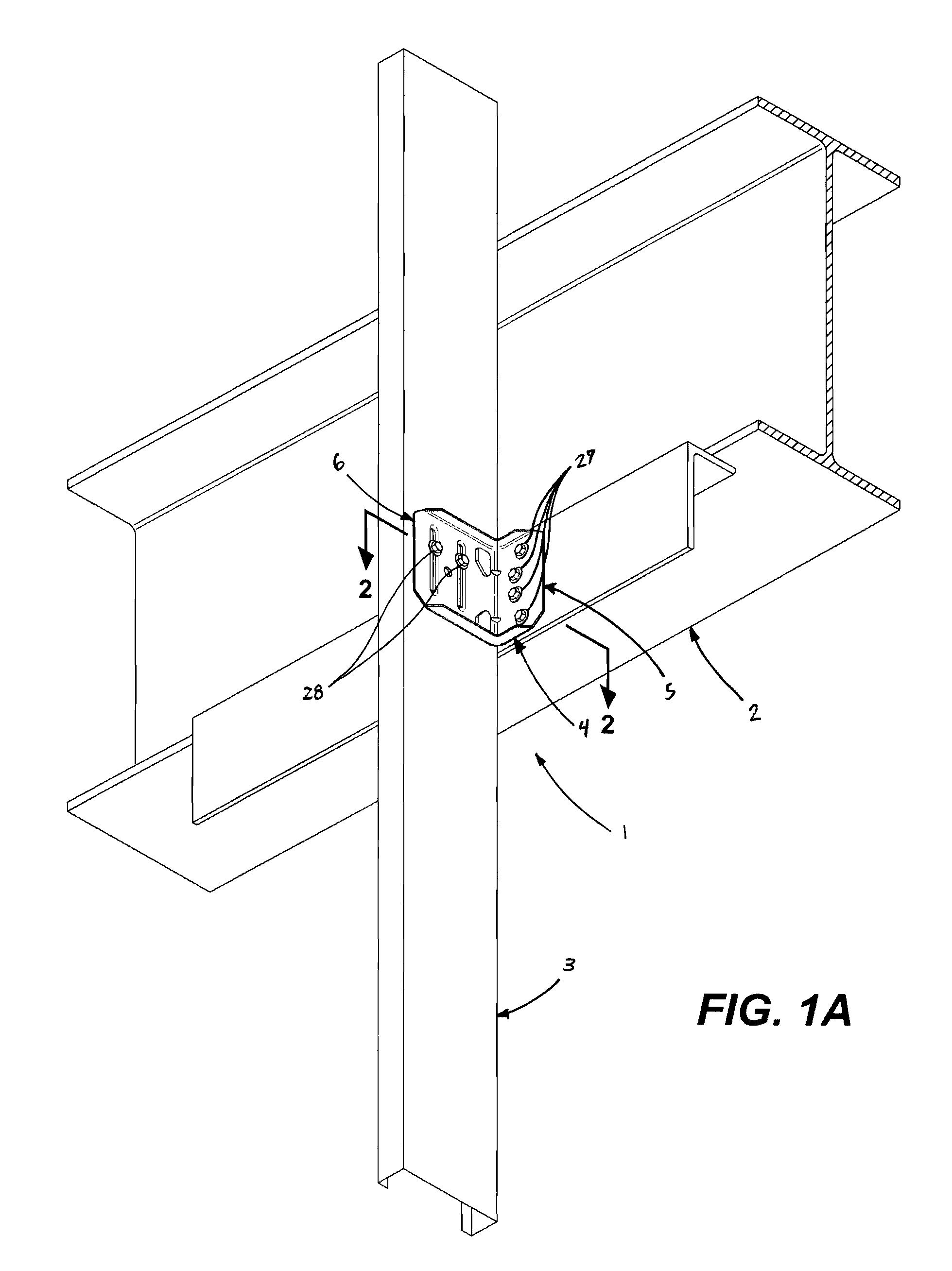
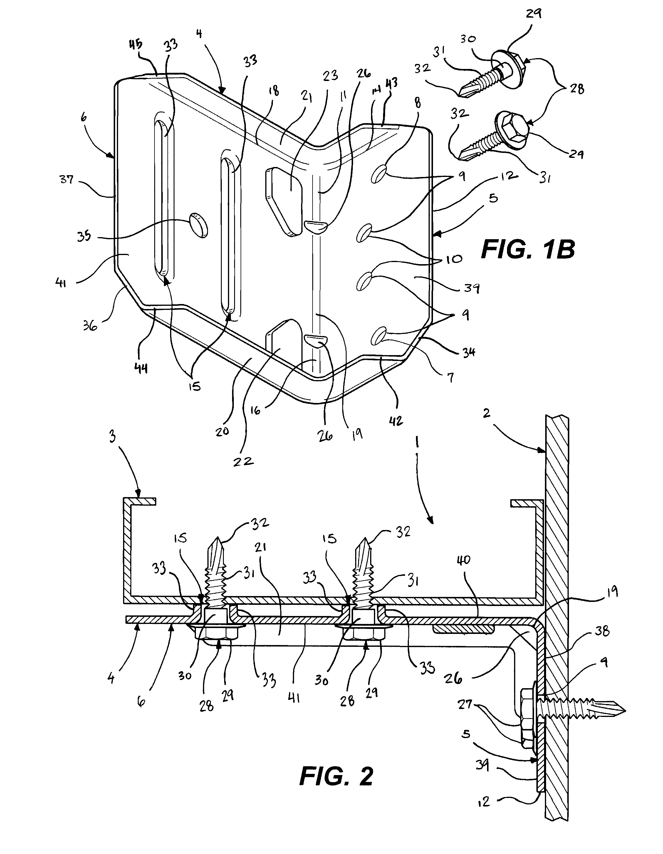
[0039]The present invention is a building structural connection 1 between a first building structural member 2 and a second building structural member 3. Preferably, the first building structural member 2 is a supporting member 2 and the second building structural member 3 is a supported structural member 3. As shown in FIGS. 1A and 8A, the first building structural member 2 is a horizontal beam with an attached ledger 2 and the second building structural member 3 is a vertically-oriented channel-shaped wall post 3. As shown in FIG. 5A, the first building structural member 2 is a horizontal beam with an attached vertically-oriented channel-shaped header 2—the second building structural member 3 is a vertically-oriented channel-shaped wall post 3. As shown in FIG. 11A, the first building structural member 2 is a horizontal beam 2 and the second building structural member 3 is a vertically-oriented channel-shaped wall post 3.

[0040]The connection 1 between the first building structural...


PUM


Abstract

An improved connection between supporting and supported structural members, particularly between the sheathing and framing members of curtain walls.

Description

BACKGROUND OF THE INVENTION[0001]The present invention belongs to a class of stud mounting clips that are useful in the construction of buildings, particularly light commercial buildings.[0002]Many buildings are constructed with steel stud wall systems in order to achieve reduced environmental concerns, fire safety and reduced susceptibility to warpage, infestation, rust and rot. For a variety of reasons, it is often advantageous to construct these walls systems with connectors that permit a degree of relative movement between the framing members. Buildings often settle on their foundations once constructed, which can cause exterior walls to go out of plumb, in turn causing damage to the surrounding foundation and to interior structures such as floors. Exterior walls and frames, particularly of light commercial buildings, are often made from materials that have different coefficients of expansion than that of the structure's exterior sheathing. With exposure to extremes of temperatu...

Claims


Application Information

Patent Timeline
Patent Type & Authority Patents(United States)
IPC IPC(8): E04B2/30
CPCE04B1/2403E04B2/768E04B2001/2448E04B2001/2439E04B2001/2415
Inventor DAUDET, LARRY RANDALLLIN, JIN-JIESTAUFFER, TIMOTHY M.DING, FRANK X.OELLERICH, PAUL HOWARDGOODMAN, CHRISTOPHER S.
Owner SIMPSON STRONG TIE
Learn More