
Ground contact sensing systems and methods for lower-limb orthotic and prosthetic devices

a technology of prosthetic devices and ground contact, applied in the field of system and method for sensing ground contact of prosthetic and/or orthotic devices, can solve the problems of reducing the sensitivity of inertial torque loading, affecting the performance of the device, and affecting the quality of the device, etc., and achieves the effect of reducing the sensitivity to inertial torque loading

Active Publication Date: 2013-10-15
OSSUR HF
View PDF26 Cites 12 Cited by
  • Summary
  • Abstract
  • Description
  • Claims
  • Application Information

AI Technical Summary

Benefits of technology

The patent describes a ground contact sensor for prosthetic devices that can detect the moment when the device touches the ground, called the "foot strike event". The sensor uses a special mechanical structure that reduces sensitivity to inertial loading, so it can properly measure this event even during the swing phase of the device. This helps to improve the control and performance of the device. In simpler terms, the patent presents a way to make sure that the device is in touch with the ground and can move around safely. Overall, this technology makes it easier to design and control prosthetic or orthotic devices.

Problems solved by technology

The extent of the lower-limb locomotion tasks associated with daily living activities often cannot be addressed with a single lower-limb prosthetic device behavior.
In fact, many technologies are available to perform such detection, but all present limitations.
Load cells are commonly used to perform this task, but are bulky, heavy and need periodical calibration to ensure that their no-load reading remains constant.
Piezoelectric sensors are also compact, but present limited performance as far as DC measurement capacity is concerned.
Resistive ink sensors can also be used to measure occurrence of foot strike in prosthetic system, but these are known to be fragile and present only a limited life duration in typical field operating conditions.
More specifically, computer-controlled devices with active actuation are subject to perturbation created by the foot inertia, as the system attempts to control the hip, knee or ankle behavior.

Method used


Image

  • Ground contact sensing systems and methods for lower-limb orthotic and prosthetic devices
  • Ground contact sensing systems and methods for lower-limb orthotic and prosthetic devices
  • Ground contact sensing systems and methods for lower-limb orthotic and prosthetic devices

Examples


Embodiment Construction

[0039]Certain embodiments described herein relate to a computer controlled lower-limb prosthesis, whether or not it is actuated, motorized, or fully passive. Further embodiments can also be used in other contexts, such as for certain types of lower-limb orthotic devices.

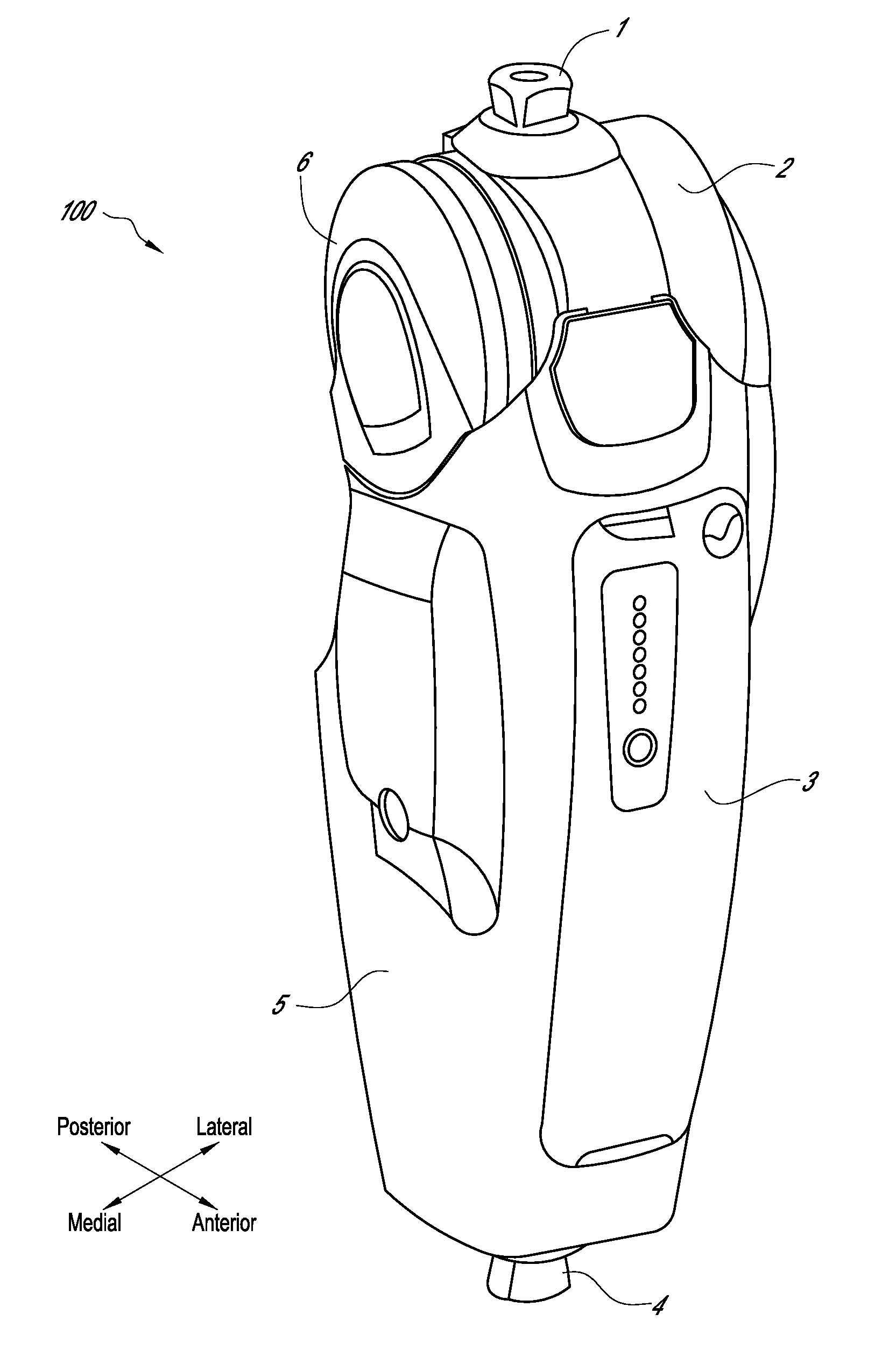
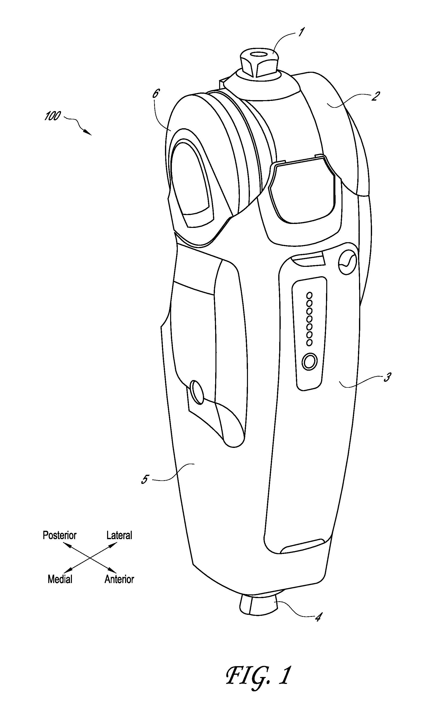
[0040]FIG. 1 illustrates one embodiment of a motorized lower-limb prosthesis 100 that can be integrated with the ground contact sensing systems described herein. It is to be noted that this specific embodiment is provided as an example and the scope of the inventions herein described apply to other embodiments, such as prosthetic feet, lower limb orthotics, sensors for non-prosthetic or orthotic use, and other devices.

[0041]The motorized lower-limb prosthesis 100 of depicted in FIG. 1 implements a knee joint and is typically connected to the user's residual limb through a socket (not shown) via the proximal end male pyramid connector 1 present on its proximal extremity. The proximal male pyramid connector 1 is secure...


PUM


Abstract

A method of sensing ground contact with a lower limb prosthetic or orthotic device is provided. A first translational displacement between a frame and a connector can be sensed and then processed to identify an axial load caused by heel-ground contact. Additionally, a second translational displacement between the frame and the connector can be sensed and then processed to identify a torsional load caused by toe-ground contact.

Description

CROSS-REFERENCE TO RELATED APPLICATIONS[0001]This application claims the priority benefit under 35 U.S.C. §119(e) to U.S. Provisional Patent Application Ser. No. 61 / 362,024 (filed 7 Jul. 2010), the entirety of which is hereby expressly incorporated by reference herein.BACKGROUND[0002]1. Field[0003]This application generally relates to systems and methods for sensing ground contact by prosthetic and / or orthotic devices.[0004]2. Description of the Related Art[0005]Advent of computer-controlled lower-limb prosthetic devices has made available to the lower-limb amputee an unprecedented realm of performance. The extent of the lower-limb locomotion tasks associated with daily living activities often cannot be addressed with a single lower-limb prosthetic device behavior. While non-computer controlled devices are relying on mechanical linkages, or mechanisms, which properties can hardly be modified to change their behavior, computer-controlled devices are quite more flexible, and assuming ...

Claims


Application Information

Patent Timeline
Patent Type & Authority Patents(United States)
IPC IPC(8): A61B5/00
CPCA61F2/64A61F2/68A61F2002/701A61F2002/705A61F2002/7625A61F2002/763A61F2002/7635A61F2002/764A61F2002/7645A61F2/70
Inventor LANGLOIS, DAVIDLANDRY, DAVIDGILBERT, BENOIT
Owner OSSUR HF
Learn More