Three dimensional radar antenna method and apparatus

a three-dimensional radar and antenna technology, applied in the direction of antennas, instruments, measurement devices, etc., can solve the problems of over $2 billion in bird strikes each year, nearly 200 people have been killed or injured, and daily collisions of birds with planes, etc., and achieve the effect of low cos

Inactive Publication Date: 2013-10-15
PIESINGER GREGORY HUBERT
View PDF89 Cites 25 Cited by
  • Summary
  • Abstract
  • Description
  • Claims
  • Application Information

AI Technical Summary

Benefits of technology

[0007]Briefly, to achieve the desired object of the present invention, a vertically oriented offset parabolic cylindrical receiving antenna is implemented. Using an a...

Problems solved by technology

Aviation experts say bird-plane collisions happen daily.
Nearly 200 people have been killed or injured since 1990 in accidents involving airc...

Method used


Image

  • Three dimensional radar antenna method and apparatus
  • Three dimensional radar antenna method and apparatus
  • Three dimensional radar antenna method and apparatus

Examples


Embodiment Construction

[0017]The goal of the present invention is to provide a low cost high gain receiving antenna with very low sidelobes that can be scanned mechanically in azimuth and scanned electronically in elevation.

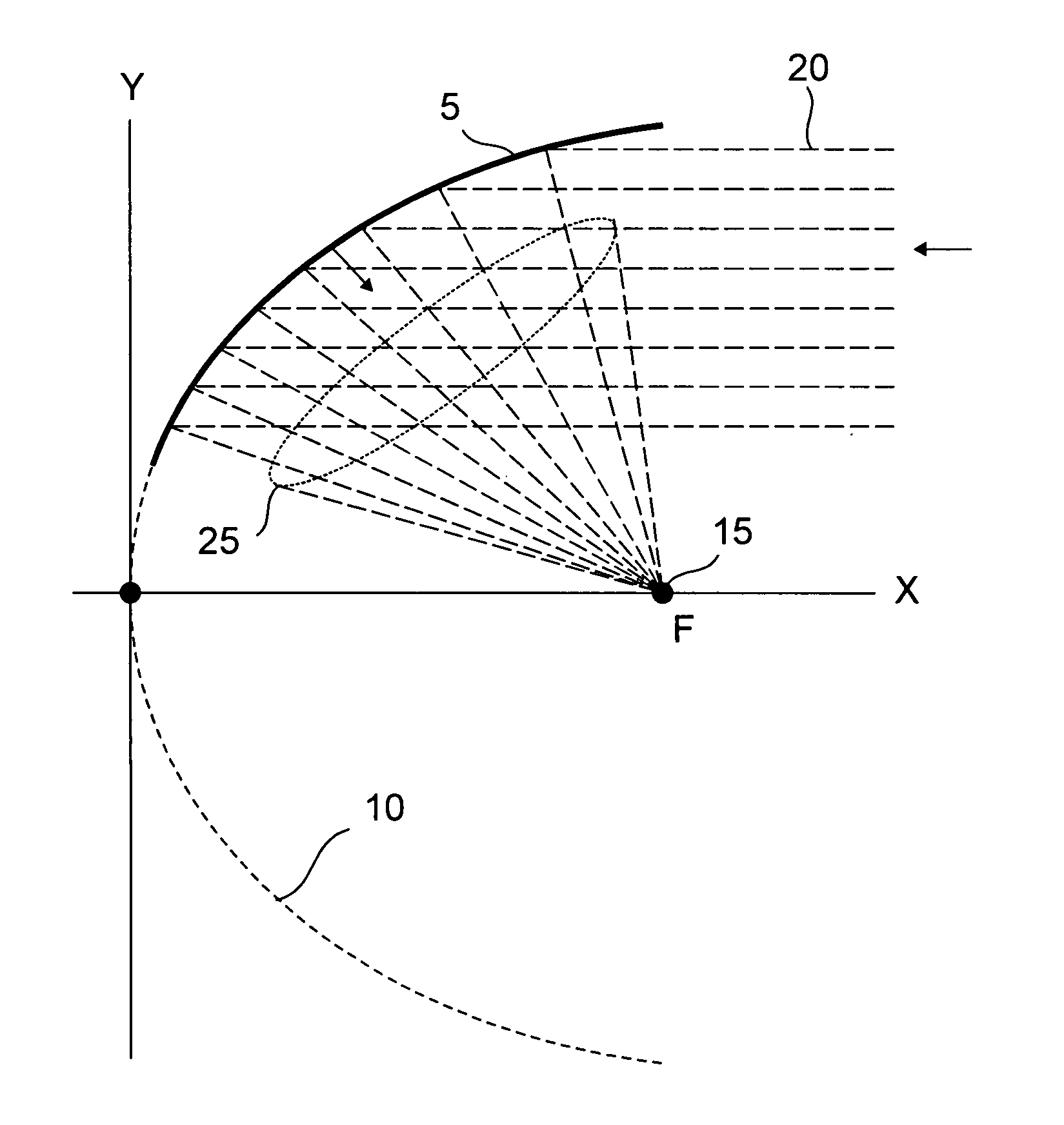
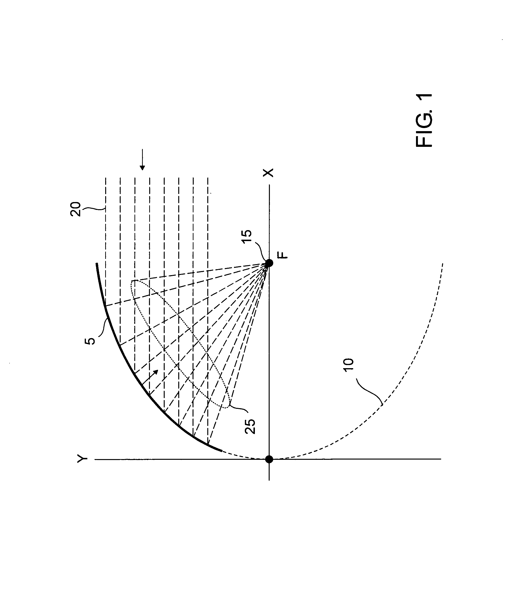
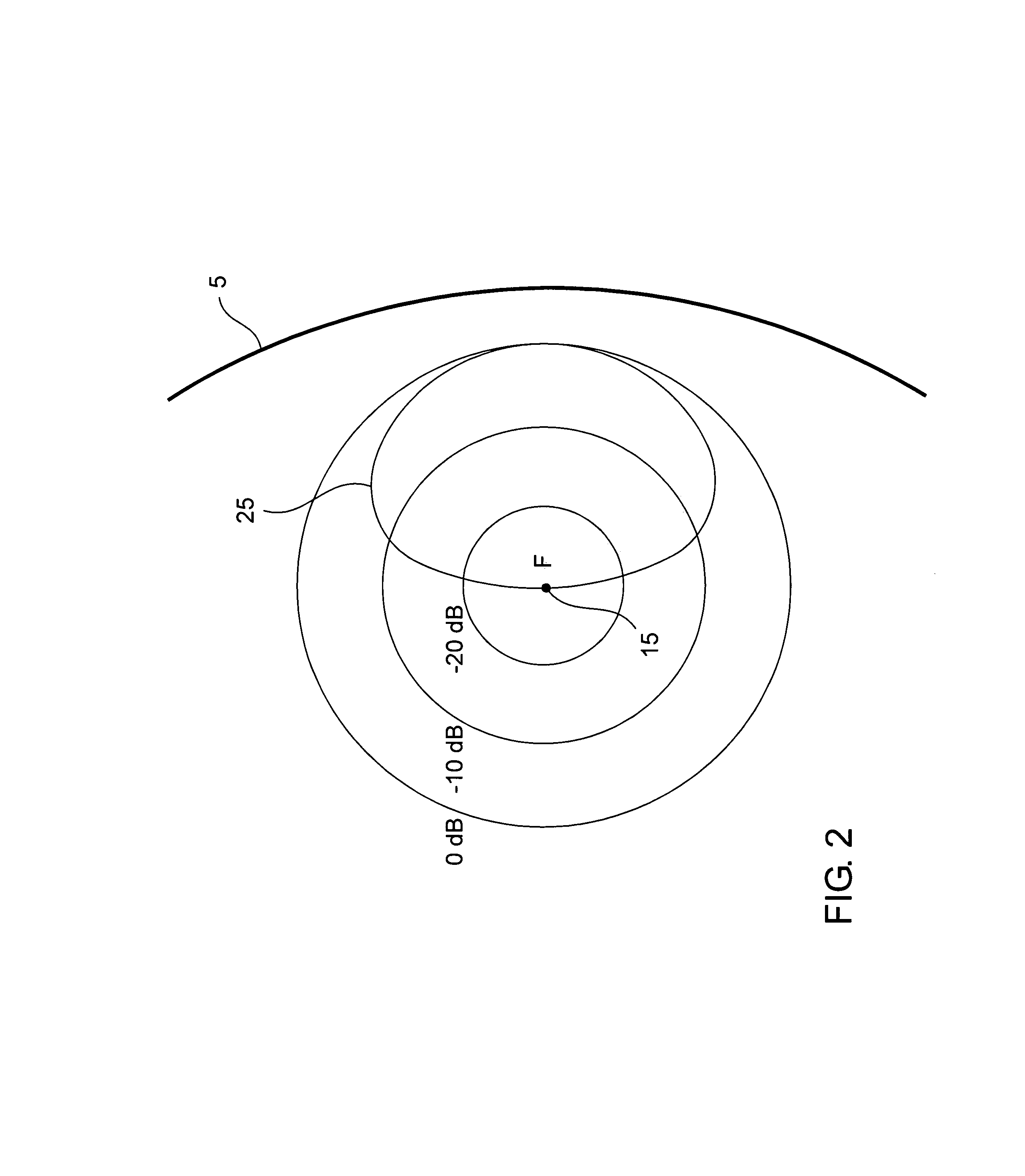
[0018]A horizontal cross section of a vertically oriented offset parabolic cylinder antenna with vertical focal line 15 is illustrated in FIG. 1. A parabolic curve is formed in the x, y plane and extended in the z plane normal to the drawing to create a parabolic cylinder. Parabolic cylinder reflector surface 10 is eliminated leaving parabolic cylinder reflector surface 5. Incoming waves 20 are focused onto focal line 15 and collected by an array of antenna elements along focal line 15 using azimuth illumination pattern 25. Removing parabolic cylinder reflector surface 10 forms an offset parabolic cylinder antenna in which antenna elements do not obstruct incoming waves 20.

[0019]As is well known by those skilled in the art, the gain of an offset parabolic cylinder antenna is governed b...


PUM


Abstract

A ground based avian radar receive antenna is implemented using a vertically oriented offset parabolic cylindrical antenna. The desired azimuth beamwidth is determined by the width of the parabolic cylinder reflector surface and the desired elevation beamwidth by the height of the parabolic cylinder reflector surface. A vertical array of antenna elements is mounted along the vertical focal line to provide electronic scanning in elevation. Low sidelobe levels are obtained using tapered antenna element illumination. Low cost modular construction with high reflector accuracy is obtained by attaching a thin metal reflector to thin ribs machined or stamped in the shape of the parabolic cylinder reflector surface. The antenna is enclosed in a radome and mechanically rotated 360 degrees in azimuth.

Description

RELATED INVENTION[0001]The present invention claims priority under 35 U.S.C. §119(e) to: “3D Radar Antenna Method and Apparatus” Provisional U.S. Patent Application Ser. No. 61 / 271,546, filed 22 Jul. 2009 which is incorporated by reference herein.TECHNICAL FIELD OF THE INVENTION[0002]The present invention relates to the field of three-dimensional (3D) radar. More specifically, the present invention relates to the field of 3D avian radar for detecting, determining height, and tracking birds.BACKGROUND OF THE INVENTION[0003]Aviation experts say bird-plane collisions happen daily. Nearly 200 people have been killed or injured since 1990 in accidents involving aircraft and wildlife. It is estimated that bird strikes cost military and commercial aviation over $2 billion each year due to damage and other costs.[0004]Airports take a variety of measures to reduce bird populations near major airports. In a few cases, ground based avian radars are used to detect flying birds near aircraft app...

Claims


Application Information

Patent Timeline
IPC IPC(8): G01S13/08H01Q15/20H01Q15/14H01Q21/00H01Q19/12H01Q19/10H01Q13/00H01Q21/08H01Q19/06G01S13/00
CPCH01Q3/04H01Q3/245H01Q25/007H01Q19/175G01S7/03G01S13/88H01Q15/14
Inventor PIESINGER, GREGORY HUBERT
Owner PIESINGER GREGORY HUBERT
Why Eureka
Try Eureka