Sports bottle with preloaded valve and methods

a valve and valve body technology, applied in the field of bottles, to achieve the effect of easy cleaning, resistance to leakage and noise, and partial resistance to leakage occurring

Inactive Publication Date: 2013-10-22
LEONOFF CHRISTOPHER A
View PDF29 Cites 14 Cited by
  • Summary
  • Abstract
  • Description
  • Claims
  • Application Information

AI Technical Summary

Benefits of technology

[0023]It is another object of the present invention to provide a valve of particular resistance to leakage occurring from residues and particulates of modern, supplemented sports beverages.
[0024]It is a further object of the present invention is to provide a bottle and valve configuration resistant to leakage and noise caused by shock forces encountered in sports and cycling.
[0025]It is yet another object of the present invention to provide a valve assembly with a sealing junction unhindered by varying wall thicknesses and seams of container bottom-walls.
[0026]It is still another object of the present invention to provide a valve assembly easily cleaned without removal and disassembly, thereby increasing the convenience and frequency of routine cleaning.
[0027]It is still another object of the present invention to provide a valve with a simplified mounting configuration thereby reducing manufacturing costs.
[0028]It is still another object of the present invention to provide a smooth singular valve component in contact with the beverage, minimizing crevices that potentially harbor residues, particulates, and bacteria.

Problems solved by technology

However, maintaining an effective leak seal has been difficult to achieve.
Multiple prior bottles have been patented which include bottom-mounted valves intended to improve the dispensing and flow aspects of the container, but effective prevention of leakage has been elusive.
The properties of these liquids present immense sealing challenges for check valves, and have a tendency to cause leakage failure in such prior art bottles.
However, the inside wall, and in particular, the inside bottom-wall is subject to a significant and unpredictable variation in wall thickness, and in many bottles, an uneven seam.
Hence far, the following problems have made effective sealing and market success elusive: a) Valve structure susceptible to the formation of leak paths b) Valve structure susceptible to shock forces c) Inconvenient cleaning d) Modern sports liquids contaminating valve sealing faces e) Valve distortion due to mounting within uneven container bottom-walls.
However, neither of these patents accomplishes an affirmative valve, or seal, closure, thus they are not suitably effective for preventing leakage of sports liquids.
a) The configuration of the valve is vulnerable to leakage when used with impure, sports liquids. It is well known that umbrella, or disc, valves are highly dependent upon a high degree of surface flatness to accomplish an effective seal. This is partially due to the rigid nature of the seating surface. However, when such valves are used with sports beverages, residues and films easily build upon the seating surface, altering its surface properties and permitting leak paths to form. With the valve being beneath the fluid level of the container, liquid pressure causes the valve to leak. Flinn makes no reference to sports beverages that cause these problems, which are widely used in sports bottle market. Additional well known disadvantages of the type of valve used in the Flinn patent are: a) Both components are separately constructed, thus the fitting between the two components is highly susceptible to surface finish and alignment problems. b) The circumferential length and width of the seating surface results in a relatively broad critical sealing area, increasing the potential for leak paths to form. c) One component of the seal is compliant, while the other is rigid.
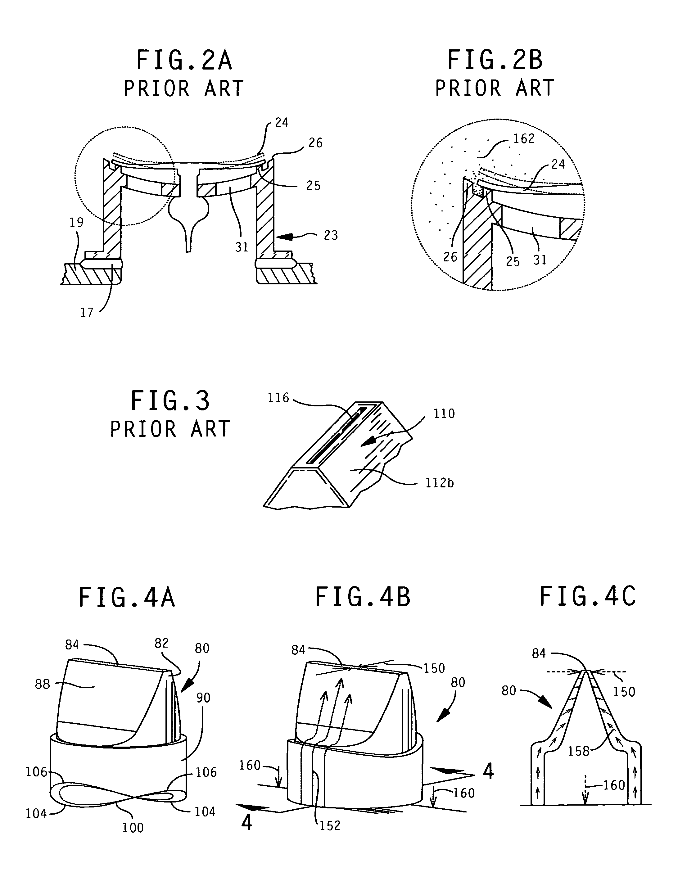
b) The configuration of the valve is vulnerable to leakage caused by shock forces. Flinn's valve actuates in a vertical orientation, which is highly problematic when the container encounters shock forces commonly exerted upon bottles in bottle holders on bicycles. The shock forces cause an upsetting of the valve, permitting small air charges to enter the container, thereby permitting liquid to breach the valve seal. If particulates lodge within the seal, leakage is imminent; otherwise sports liquids will begin to form a layer of residue within the seal face, altering its flatness properties, allowing leak paths to eventually form. These air charges, and breaching, also cause an audible popping, or clicking, noise which is distracting for cyclists.
c) The valve sealing junction is difficult to access for cleaning, unless it is removed. Both Vinciguerra, and Flinn refer to disassembly in order to facilitate cleaning, as Flinn maintains in column 5, lines 7-9. However, this disassemble-to-clean method is inconvenient and adds a step when compared with cleaning an ordinary sports bottle. Thus making it inconvenient to maintain a clean bottle and valve, and further increasing the likelihood of leakage.
d) The shape of the valve and the seating surface promote the gathering of settled particulates near the valve's critical sealing junction. Due to its flat profile and annular crevice, particulates settle near the critical sealing junction of the valve, making it particularly vulnerable leakage caused by particulates binding within the sealing face.
e) The complexity of the valve mechanism increases the bottle's cost and reduces its reliability. Flinn states at column 4, lines 23-36, that the preferred method of attachment of the valve housing to the container is by ultrasonic welding. Flinn also discloses an alternate mounting approach by threading. However, both of these methods and add steps and cost to manufacturing.
a) They are not suited for a cylindrical push-in, gasket type mounting.
b) They are not configured for an even circumferential compression mounting, and have uneven lateral pressure within hole mounting applications.
c) They require substantial and uneven lateral compression to accomplish preloading, causing substantial distortion of the valve body, further causing mounting difficulties and fitting complexities.
d) They are not configured for mounting within varying, unpredictable wall thicknesses. Such uneven wall thicknesses cause sealing, mounting, and distortion problems when interacting with fixed size grooved, or snap-in, mounting features of such duckbill valves.
e) They are either suited for inward lateral preloading, or outward lateral preloading, but not both; thus, their non-circular nature is overly complex for gasket style mounting.
f) Hofsteenge and Atkinson show external ribs on the valve panels that require additional supportive structure to function properly, this structure would be undesirable within the bottom of a sports bottle, as well as difficult to clean.

Method used


Image

  • Sports bottle with preloaded valve and methods
  • Sports bottle with preloaded valve and methods
  • Sports bottle with preloaded valve and methods

Examples


Embodiment Construction

[0046]FIG. 1 is an exploded, side perspective view of one embodiment of the invention. It consists of a mouthpiece 20, a lid 30, a vessel 50, a valve 80, and an insert 120.

[0047]Mouthpiece 20 consists of a dispensing opening 21, a fluid passage 22, a lip 27, sealing rings 28, and barbs 29. Mouthpiece 20 is preferably injection molded from a soft plastic, or a firm rubber material permitting sealing rings 28, dispensing opening 21, and barbs 29 to be moderately compressible. The soft material also provides comfortable interaction between mouthpiece 20 and a user's mouth and teeth.

[0048]Lid 30 consists of a top wall 32, an annular bore 34, a tapered ridge 36, internal threads 38, and stopper plug 39. Lid 30 is preferably injection molded from a material such as high-density polyethylene (HDPE), or similar material.

[0049]A lid assembly designated generally by the number 40 comprises the combined mouthpiece 20 and lid 30, which is joined by compressing mouthpiece 20 within annular bore ...


PUM


Abstract

A beverage bottle for storing and dispensing water and impure sports beverages having a container and a dispensing opening on a top wall movable between an open position and a closed position and a unitary valve disposed within the container bottom wall having a vertically sinuous contour, and laterally opposed, laterally actuating, compliant slit faces and a substantially rigid annular flat surface. As the vertically sinuous contour is flattened upon the annular flat surface, the slit faces are laterally urged together establishing a preloaded seal, for leak resistant valve operation, and reduced restriction dispensing of water and impure sports beverages.

Description

CROSS-REFERENCE TO RELATED APPLICATIONS[0001]This application is a continuation-in-part of application Ser. No. 12 / 054,307 filed Mar. 24, 2008, entitled “Rapid Flow Bottle”, which claims the benefit of provisional patent application Ser. No. 60 / 896,763 filed Mar. 23, 2007 entitled “Rapid Flow Bottle” by the present inventor.FIELD OF THE INVENTION[0002]The present invention relates to bottles, and more specifically, to sports bottles intended for use during sports activities and with sports beverages.BACKGROUND OF THE INVENTION[0003]It is known that by venting air within a sports bottle, various flow characteristics may be improved. However, maintaining an effective leak seal has been difficult to achieve. Multiple prior bottles have been patented which include bottom-mounted valves intended to improve the dispensing and flow aspects of the container, but effective prevention of leakage has been elusive.[0004]The use of modern, highly supplemented, sports performance drinks, or sport...

Claims


Application Information

Patent Timeline
Patent Type & Authority Patents(United States)
IPC IPC(8): B65D37/00
CPCB65D47/243F16K15/144B65D2205/00B65D2231/005F16K15/147Y10T137/7883Y10T137/7889
Inventor LEONOFF, CHRISTOPHER A.
Owner LEONOFF CHRISTOPHER A
Why Eureka
Try Eureka