
Method for conducting electrosurgery with increased crest factor

a technology of crest factor and electrosurgical power, applied in the field of surgical methods and equipment, can solve the problems of affecting the healing process at the surgical site, affecting the safety and effectiveness of crest factor, and killing the remaining tissues, etc., to achieve the effect of enhancing the safe and effective crest factor, reducing or preventing smoke production, and/or tissue damag

Active Publication Date: 2013-10-22
SURGINETICS
View PDF102 Cites 3 Cited by
  • Summary
  • Abstract
  • Description
  • Claims
  • Application Information

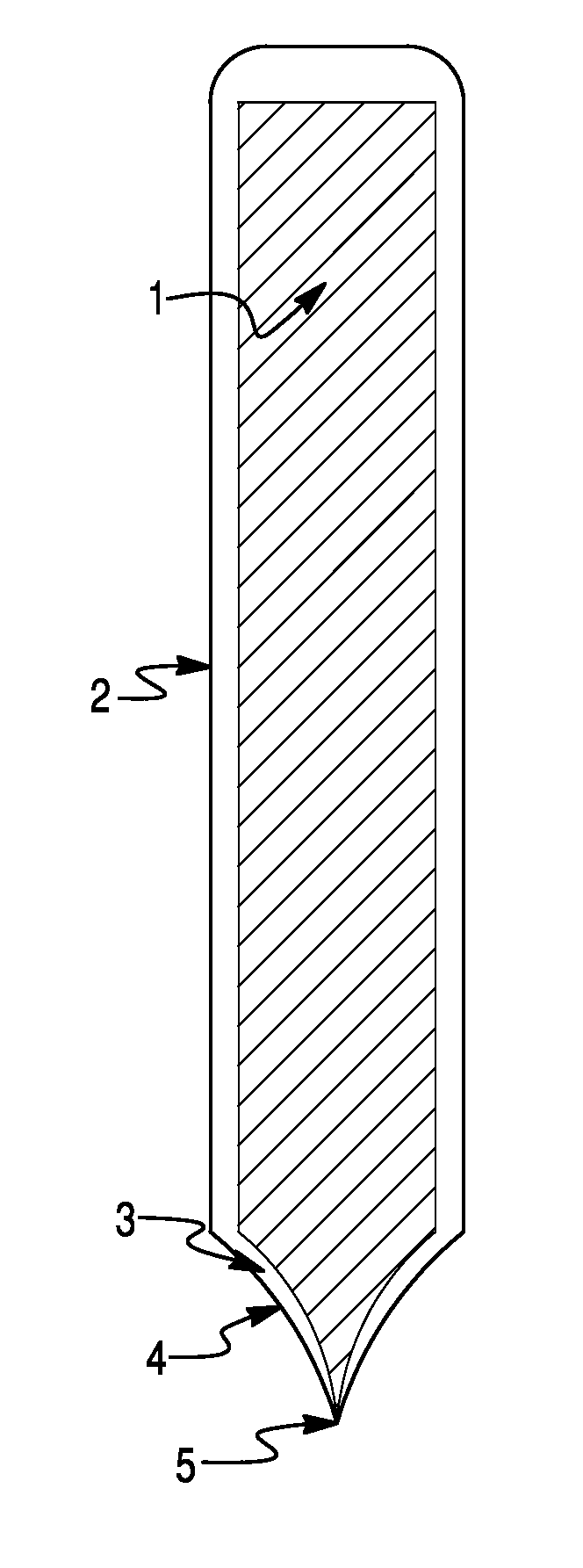
AI Technical Summary

Benefits of technology

[0010]Various embodiments provide a method for conducting electrosurgery with higher crest factors, which is the ratio of the peak voltage to the root mean square (RMS) voltage applied to tissue. By increasing the safe and effective crest factor, enhanced therapeutic effects are enabled.
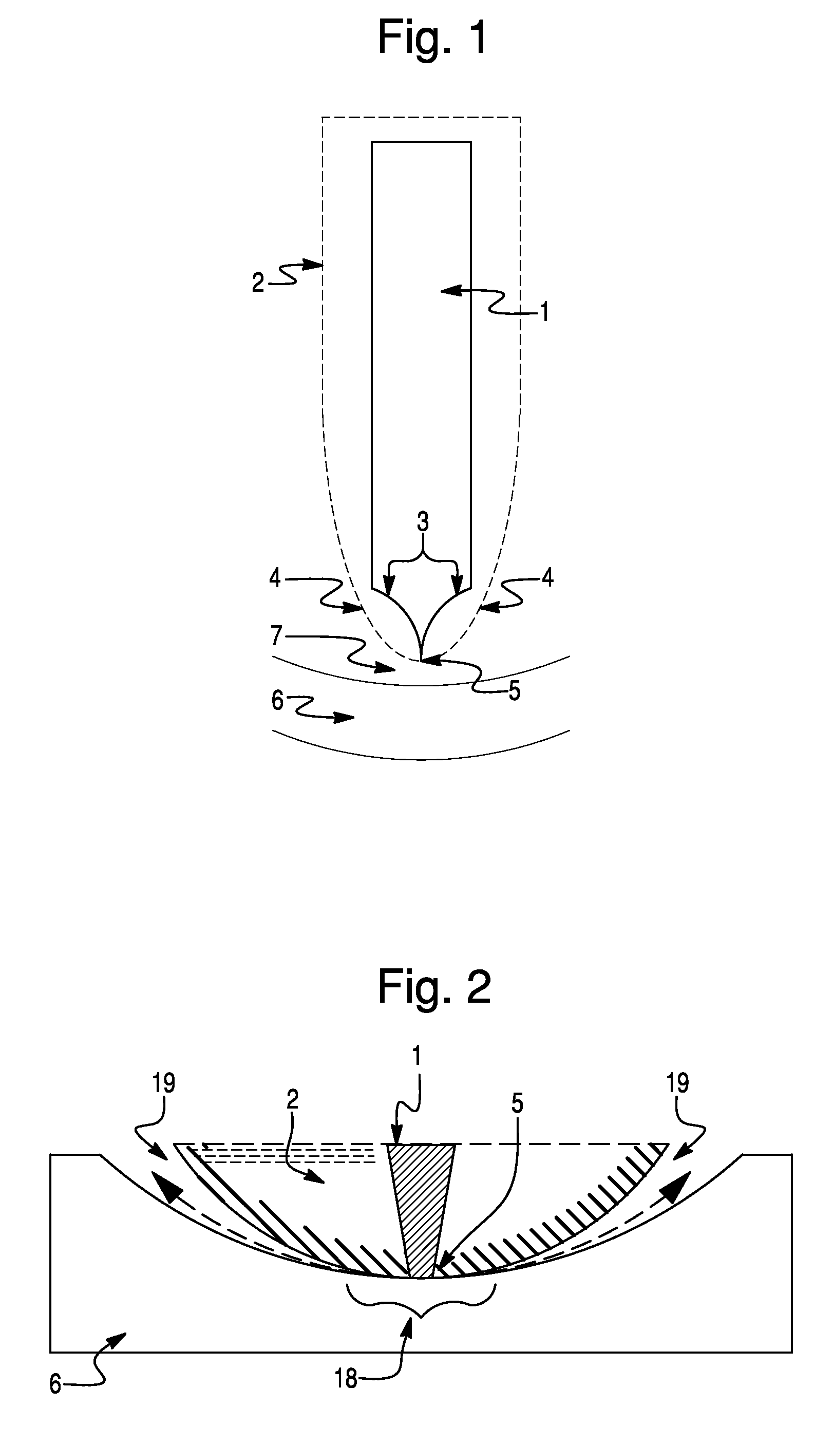
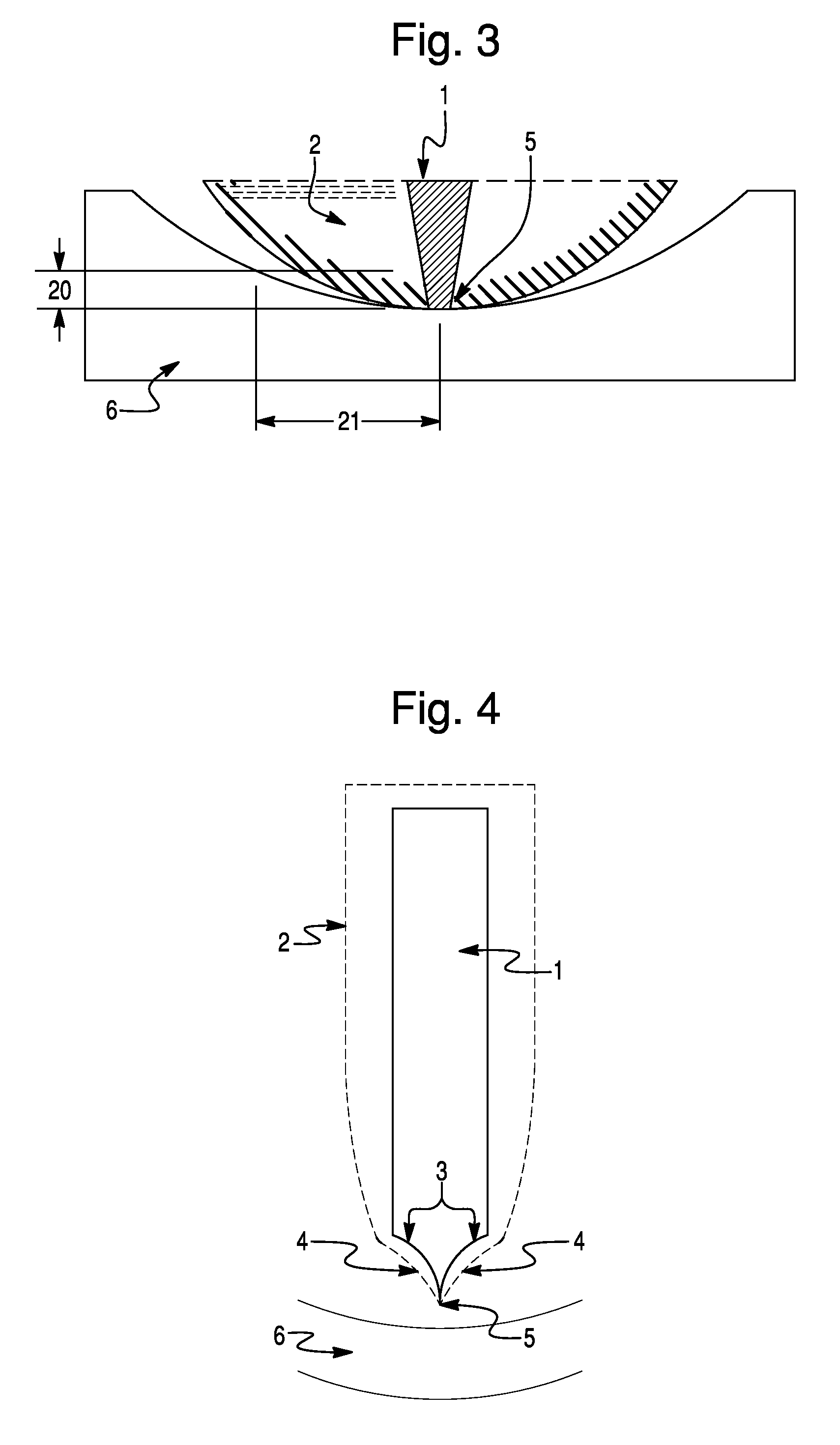
[0011]The various embodiments use electrosurgical instruments having a blade geometry, blade composition or a combination of blade geometry and composition that concentrates electrosurgical energy and reduces or prevents smoke production, eschar accumulations, and / or tissue damage. The embodiment instruments focus electrosurgical energy to a small amount of tissue for a short duration compared to the amount of tissue and duration than is customary during electrosurgery using conventional technology. Various embodiments yield less eschar accumulation on the electrosurgical instrument by providing an exterior surface of the instrument with a shape that facilitates movement of tissue decomposition products away from the active region of the conductive element. The active region is a region on the conductive element where electrosurgical energy transfers from the blade to tissue. In some embodiments, the tapered configuration includes an electrically conductive element with a tapered section. In some embodiments, the tapered configuration includes configuring an insulating layer with a tapered section. In various embodiments, insulation on the conductive element has a surface free energy that reduces the propensity for electrosurgical decomposition products (defined herein) to stick to the surface. In various embodiments, the shape of the blade minimizes the duration that the active region is near any particular portion of tissue as the blade is moved through tissue as during an incision.

Problems solved by technology

The tissue changes at the surgical site, such as charring, interfere with normal metabolic processes and, for example, kill tissues that remain at the surface of incisions.
The changes in tissues caused by electrosurgical energy, such as killing parts of tissues, are known to interfere with healing at the surgical site.
Beyond damaging tissue at the surgical site, conventional electrosurgery has other drawbacks which limit its applicability or increase the costs and duration of procedures.
Smoke obscures the field of view and hinders surgical procedures and is also a known health hazard.
Controlling smoke once it has formed is problematic, requiring the evacuation of large volumes of air in order to capture an appreciable fraction of the smoke with wands that are close to the surgical site where they are in the way, and adds costs in both additional equipment and labor.
Eschar inhibits the effectiveness of electrosurgical devices and must frequently be removed, hindering surgical procedures.
Despite advances in the field, electrosurgical blades continue to suffer from one or more of the problems of producing smoke, having materials from tissues coat the blades, and damaging tissue.
Likewise, prior art electrosurgical blades did not consider the conductive pathways that can be formed by tissue fragments adhering to blades and the effects that these built-up conductive pathways have on producing smoke, producing more materials that can further coat blades, and the effects that these have during electrosurgery.
The aforementioned limitations in conventional electrosurgery impose limits on the peak voltage that can be applied to tissue during electrosurgery.

Method used


Image

  • Method for conducting electrosurgery with increased crest factor
  • Method for conducting electrosurgery with increased crest factor
  • Method for conducting electrosurgery with increased crest factor

Examples


Embodiment Construction

[0028]The various embodiments will be described in detail with reference to the accompanying drawings. Wherever possible, the same reference numbers will be used throughout the drawings to refer to the same or like parts.

[0029]As used herein, the terms “about” or “approximately” for any numerical values or ranges indicates a suitable dimensional tolerance that allows the part or collection of components to function for its intended purpose as described herein. Also, as used herein, the terms “patient”, “tissue” and “subject” refer to any human or animal subject and are not intended to limit the systems or methods to human use, although use of the subject invention on a human patient represents a specific embodiment.

[0030]All devices that may be used to produce a predetermined surgical effect by applying RF power to tissue may be referred to herein as electrosurgical “blades” due to their function of partial or complete removal of one or more parts of tissue (including changing the s...


PUM


Abstract

A method for conducting electrosurgery using increased crest factors employs an electrosurgical instrument having at least one conductive element that is surrounded by an insulation layer except at a conductor edge portion of the conductive element. The conductor edge portion and insulation layer each having unique geometric shapes and composition of the parts concentrate the electrosurgical power, reduce or eliminate the production of smoke and eschar and reduce tissue damage. The outer profile of the insulation layer and conductive element are configured to facilitate the flow of electrosurgical decomposition products away from the conductor edge where they are formed. The combined effects of the electrosurgical instrument configurations enable safe use of crest factors of 5 or greater in electrosurgical procedures.

Description

[0001]This application claims the benefit of priority to U.S. Provisional Application 60 / 695,692 entitled Multielectrode Electrosurgical Instrument filed Jun. 30, 2005, the entire contents of which are hereby incorporated by reference.FIELD OF THE INVENTION[0002]The present invention relates to surgical methods and apparatus, and more particularly to applying electrosurgical power to a tissue site to achieve a predetermined surgical effect.BACKGROUND OF THE INVENTION[0003]The potential applications and recognized advantages of employing electrical energy in surgical procedures continue to increase. In particular, for example, electrosurgical techniques are now being widely employed to provide significant localized surgical advantages in open, laparoscopic, and arthroscopic applications, relative to surgical approaches that use mechanical cutting such as scalpels.[0004]Electrosurgical techniques typically entail the use of a hand-held instrument that contains one or more electrically...

Claims


Application Information

Patent Timeline
Patent Type & Authority Patents(United States)
IPC IPC(8): A61B18/14
CPCA61B18/1402A61B2018/00083
Inventor HEIM, WARREN P.BRASSELL, JAMES L.
Owner SURGINETICS
Learn More