Power amplifier

a power amplifier and amplifier technology, applied in amplifiers, amplifiers with semiconductor devices/discharge tubes, electrical devices, etc., can solve the problems of reducing to a certain extent the operational frequency bandwidth, affecting the operation of the power amplifier, so as to achieve better operation and improve operation.

a power amplifier and amplifier technology, applied in amplifiers, amplifiers with semiconductor devices/discharge tubes, electrical devices, etc., can solve the problems of reducing to a certain extent the operational frequency bandwidth, affecting the operation of the power amplifier, so as to achieve better operation and improve operation.

US8564367B2Active Publication Date: 2013-10-22AMPLEON NETHERLANDS

Image

  • Power amplifier
  • Power amplifier
  • Power amplifier

Examples


Embodiment Construction

[0035]A main principle according to embodiments of the invention disclosed herein is based on a combination of electrically connected coupled and single transmission lines in an output stage of a power amplifier comprising two or more amplifier stages providing phase shifted amplified outputs of an input signal. Coupled transmission lines are known for use as impedance transforming elements in impedance matching structures, but not as combining structures for load modulation power amplifiers such as Doherty or Chireix power amplifiers, where amplifier operation has to be guaranteed under dynamically varying load conditions.

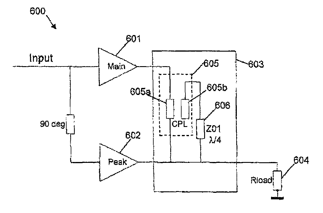
[0036]FIG. 6A illustrates a two-way symmetric Doherty power amplifier according to a first exemplary embodiment of the invention. As with the Doherty amplifier shown in FIG. 1, the amplifier comprises first and second amplifier stages 601, 602 having inputs connected to a common input signal, the second amplifier stage 602 being provided with a phase-shifted versi...


PUM


Abstract

The invention relates to improving the performance of load modulation power amplifiers through the use of coupled transmission line-based power combiners. Exemplary embodiments disclosed include a power amplifier comprising an input connected to first and second amplifier stages and an output stage configured to combine phase shifted amplified outputs from the first and second amplifier stages and to provide an amplified signal at an output of the power amplifier, wherein the output stage comprises coupled first and second transmission lines connected between the output of the first amplifier stage and an output load connection.

Description

[0001]This application claims the priority under 35 U.S.C. §119 of European patent application no. 10250822.3, filed on Apr. 23, 2010, the contents of which are incorporated by reference herein.FIELD OF INVENTION[0002]The invention relates to improving the performance of load modulation power amplifiers through the use of coupled transmission line-based power combiners.BACKGROUND OF THE INVENTION[0003]Power amplifiers (PAs) that use load line modulation techniques to improve overall amplifier efficiency have been known for some time. Two well-known examples are in the form of a two-way Doherty amplifier, illustrated in FIG. 1, and a Chireix outphasing amplifier, illustrated in FIG. 2. A two-way Doherty amplifier comprises two amplifier stages 101, 102, a first of these being a peak amplifier 101 and a second being a main amplifier 102. The peak amplifier 101 amplifies a phase-shifted version of the input signal, while the main amplifier 102 amplifies an unshifted version. A combiner...

Claims


Application Information

Patent Timeline
22 Oct 2013
Publication
US8564367B2
IPC
H03F3/68
CPC
H03F1/0288; H03F3/602; H03F1/0294; H03F2200/543
Inventors
SVECHTAROV, IORDAN KONSTANTINOV