
Back cover of LCD, backlight module and LCD

a liquid crystal display and backlight module technology, applied in the field of backlight modules and lcds, can solve the problems of difficult to ensure the quality of finished products, the inability of lcd panels to emit light by themselves, and the cost of sheet metal materials is relatively high, so as to achieve low material cost, desirable strength, and simple manufacturing

Active Publication Date: 2013-10-22
TCL CHINA STAR OPTOELECTRONICS TECH CO LTD
View PDF6 Cites 2 Cited by
  • Summary
  • Abstract
  • Description
  • Claims
  • Application Information

AI Technical Summary

Benefits of technology

[0007]A primary objective of the present disclosure is to provide a back cover of a liquid crystal display (LCD), a backlight module supported by the back cover, and an LCD comprising the backlight module. The back cover is formed of a plastic material through injection molding, so it is simple to fabricate and can reduce the material cost.
[0015]According to the present disclosure, the back cover is formed of a plastic material through injection molding or compression molding. Specifically, the inset is put into a mold for the back cover body in advance, and then the back cover is injection molded in such a way that the back cover is joined with the inset securely. Thus, the back cover is simple to fabricate and has a low material cost. Particularly, the inset made of a metal, a ceramic or a heat pipe can not only impart a desirable strength and desirable flatness to the back cover, but also have superior thermal conductivity adapted to dissipate heat generated by the backlight module timely.

Problems solved by technology

However, LCD panels cannot emit light by themselves, so they must be provided with a backlight source capable of independently providing light.
However, the sheet metal materials are relatively costly, and because fabrication of the stamping dies represents great difficulty, it is difficult to ensure quality of the finished products.

Method used


Image

  • Back cover of LCD, backlight module and LCD
  • Back cover of LCD, backlight module and LCD
  • Back cover of LCD, backlight module and LCD

Examples


Embodiment Construction

[0024]It shall be understood that, the embodiments described herein are only intended to illustrate but not to limit the present disclosure.

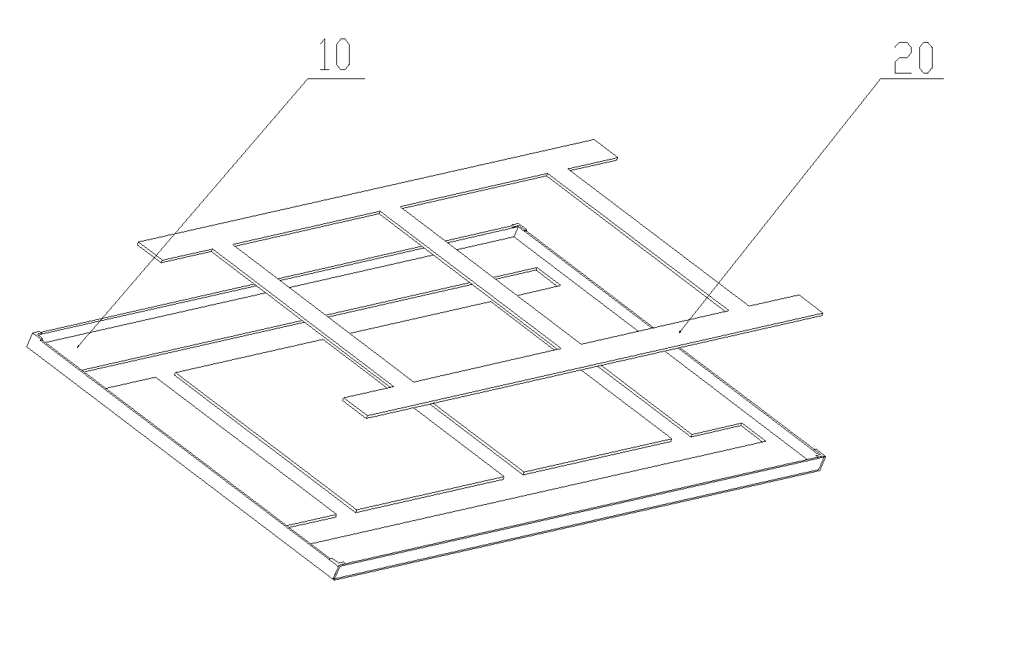
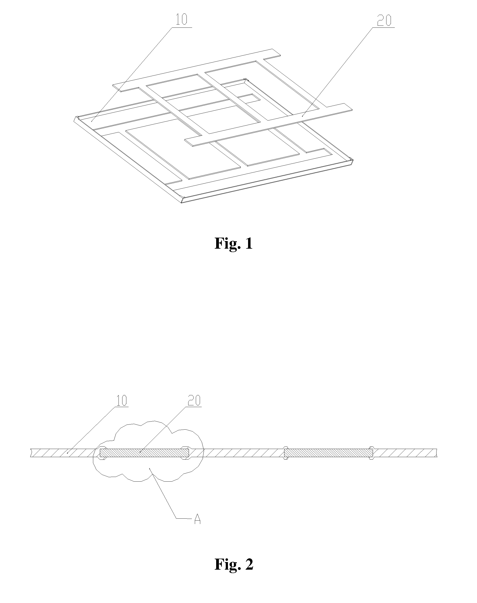
[0025]FIG. 1 is a schematic structural view illustrating a first embodiment of a back cover of an LCD according to the present disclosure. In this embodiment, the back cover of the LCD is used to support a backlight module, and is comprised of a back cover body 10 and an inset 20 inset into the back cover body 10.

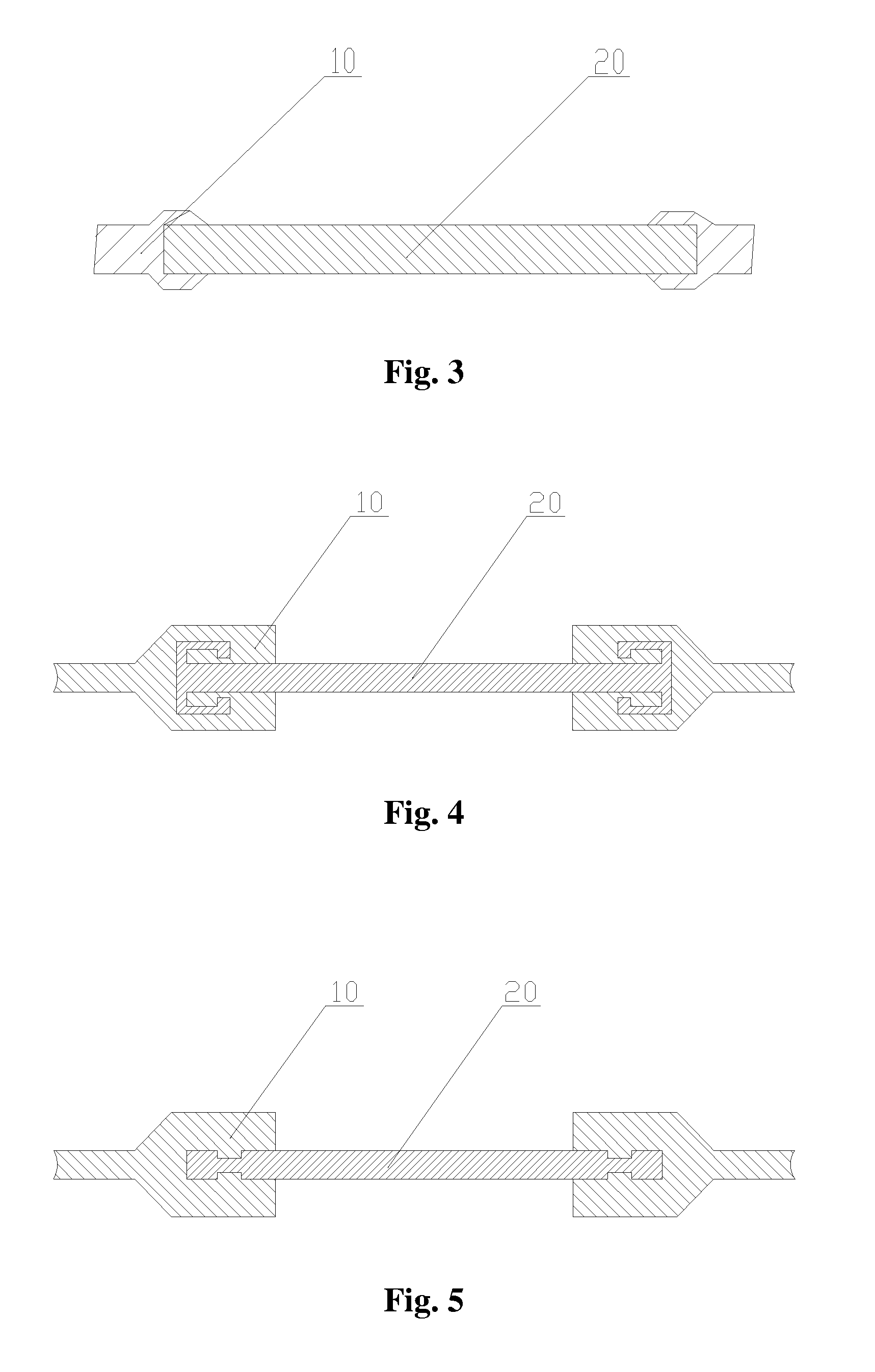
[0026]The back cover is formed of a plastic material through injection molding or compression molding. Specifically, the inset 20 is put into a mold for the back cover body 10 in advance, and then the plastic material is injected into the mold to form an assembly of the back cover body 10 and the inset 20 with the inset 20 being inset into the back cover body 10. The inset 20 is made of a material having superior thermal conductivity and a certain mechanical strength such as a sheet metal, ceramic or a heat pipe; therefore, the inset 20...


PUM

PropertyMeasurementUnit
adhesionaaaaaaaaaa
thermally conductiveaaaaaaaaaa
driving voltageaaaaaaaaaa

Abstract

A back cover of a liquid crystal display (LCD) for supporting a backlight module is disclosed. The back cover comprises a back cover body and an inset. The inset is inset into the back cover body and is of a hollow frame structure, and the inset is a sheet metal inset, a ceramic inset or a heat pipe inset. A backlight module supported by the back cover and an LCD comprising the backlight module and the back cover are also disclosed. According to the back cover of an LCD, the backlight module supported by the back cover and the LCD comprising the backlight module, the back cover is formed of a plastic material through injection molding, so it is simple to fabricate and can reduce the material cost.

Description

BACKGROUND[0001]1. Technical Field[0002]The present disclosure relates to the technical field of liquid crystal displaying, and more particularly, to a back cover of a liquid crystal display (LCD), a backlight module and an LCD.[0003]2. Description of Related Art[0004]As a kind of flat panel display devices that utilize liquid crystals to display images, liquid crystal displays (LCDs) are lighter and thinner and requires a lower driving voltage and lower power consumption as compared to other kinds of display devices. Therefore, LCDs have found wide application in various industries. However, LCD panels cannot emit light by themselves, so they must be provided with a backlight source capable of independently providing light.[0005]Generally, a back cover is used in an LCD to support the whole backlight module so that all components of the backlight module can be securely fixed. This requires that the back cover has a high strength and high flatness in order to ensure the flatness of ...

Claims


Application Information

Patent Timeline
Patent Type & Authority Patents(United States)
IPC IPC(8): G02F1/1333G02F1/1335G09F13/04
CPCH05K7/2099G02F1/13471G02F2001/133314G02F1/133314
Inventor ZHOU, GEGEHSIAO, YUCHUNZHANG, PANGLING
Owner TCL CHINA STAR OPTOELECTRONICS TECH CO LTD
Learn More