
Method for de-embedding device measurements

a technology of de-embedding and measurement method, which is applied in the direction of resistance/reactance/impedence, instruments, digital computer details, etc., can solve the problems of physical system, limited connection methods to coaxial connections, and physical systems, so as to achieve the effect of actual system and testing devi

Active Publication Date: 2013-10-22
TELEDYNE LECROY
View PDF4 Cites 130 Cited by
  • Summary
  • Abstract
  • Description
  • Claims
  • Application Information

AI Technical Summary

Benefits of technology

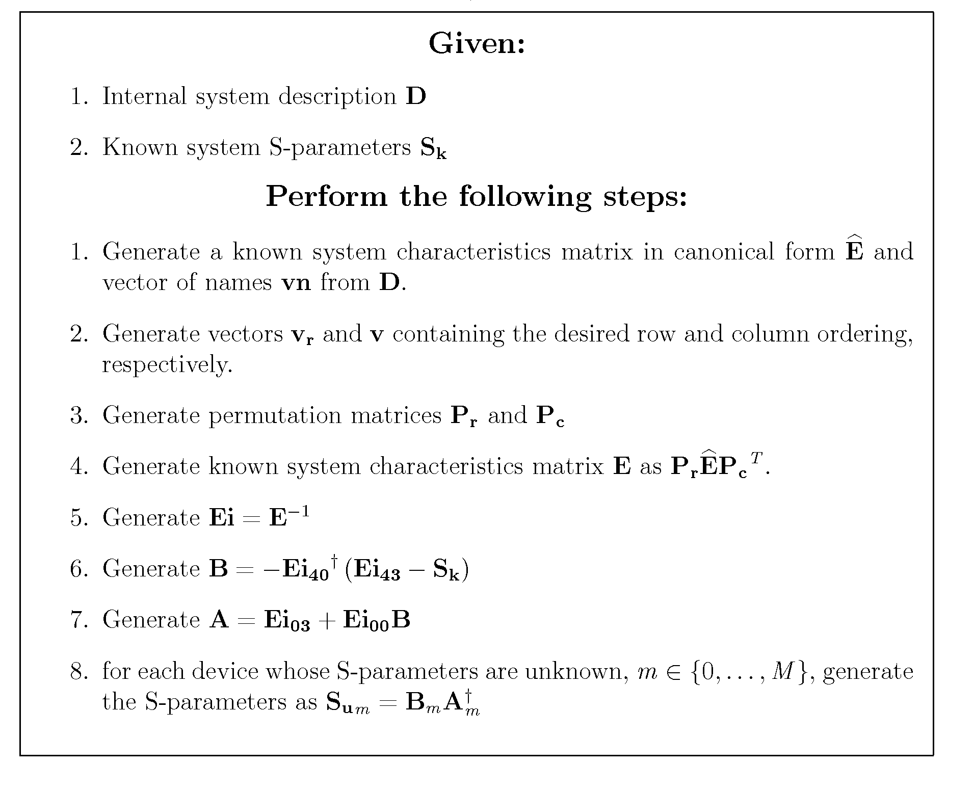
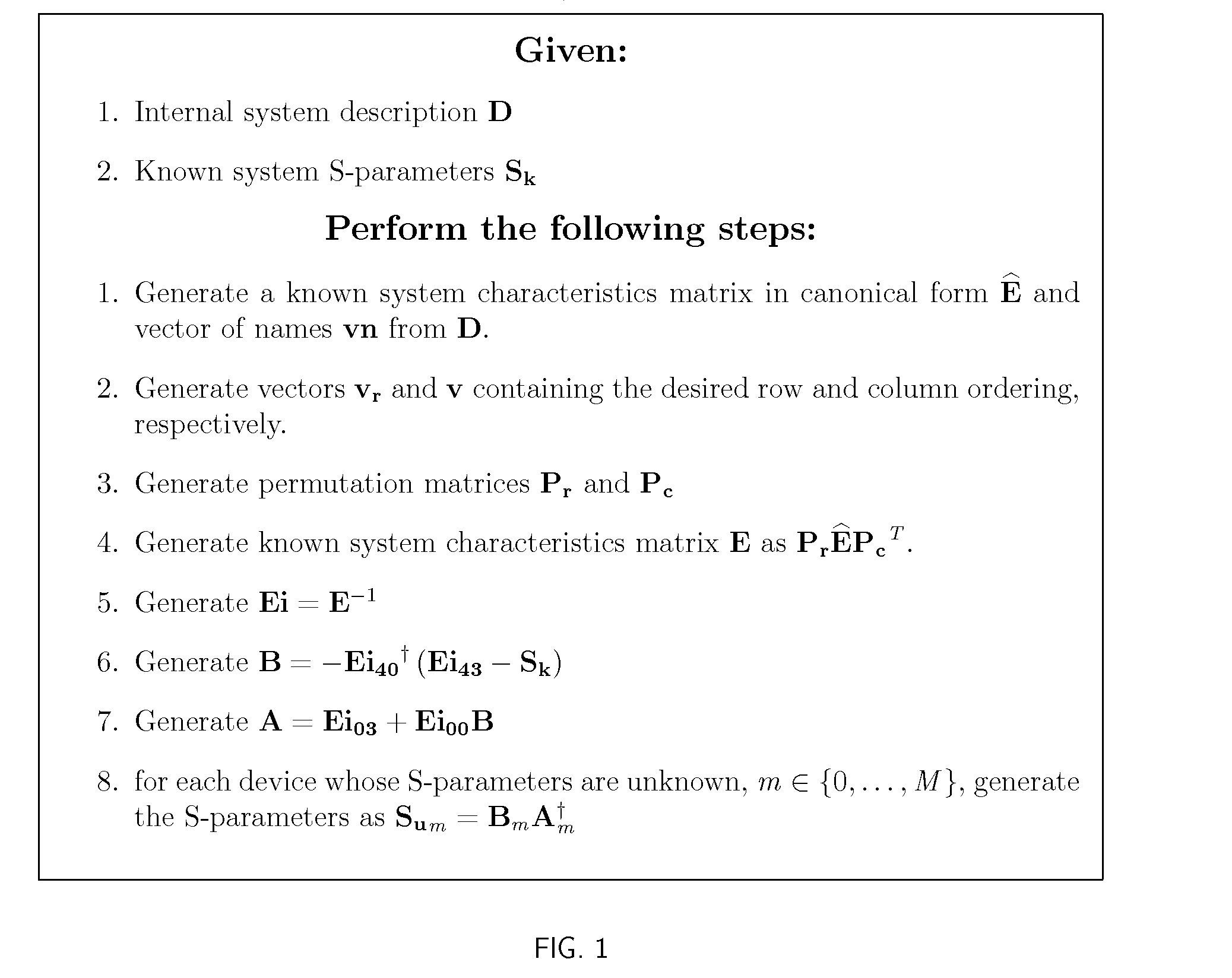
The patent describes a method to determine the measurements of unknown elements in a system using known measurements of network parameters and the interrelated connections between the known and unknown devices. The method does not require iterative analysis and solves directly in a closed-form solution for the best solution possible. It takes a net-list, a text or computer-readable description of the de-embedding problem, and known S-parameters to describe the system. The net-list is parsed and converted into an internal representation of the system, and the S-parameters of unknown elements are determined using a mathematical process. The method can handle various net- lists and de-embedding situations, including over-constrained solutions and multiple unknown elements. The invention comprises several steps and their relationships, and the apparatus embodying the features of construction adapted to affect these steps.

Problems solved by technology

One particular difficulty that arises is that both the system and the testing device are actual, physical systems.
In any such system often the connections that are made to the VNA or TDR are restricted because these systems must be built for general purpose use, and are designed in advance of any particular measurement desired by a particular user at a particular time.
Often, connection methods are restricted to coaxial connections or the sex of the connection is restricted to either male or female.
Therefore, regardless of connection capability to a DUT, often the calibration reference plane is limited to where suitable connection of standards can be made.
This method does not perform a complete de-embedding in the sense that the entire behavioral model of the DUT cannot be extracted.
In other words, gating is used to move the reference plane for some S-parameter measurements but does not move it for all measurements, and therefore does not obtain a complete de-embedded model of the DUT.
That being said, there are many examples of measurements that are too complex to be handled through this relatively simple method.
Systems are so complex nowadays that often, the way of measuring how a device will perform is to generate a model of the device and use it in a simulation.
In this case, a gated measurement is not adequate, and to get a truly accurate model, the behavioral model of the DUT needs to be de-embedded from fixturing.
Despite the fact that many methods exist for doing this, it is a problematic exercise.
Sometimes, the nature of the system makes this process difficult, such as when systems of even or odd numbers of ports are involved.
This makes the algorithm difficult to automate for any given circuit.
This approach suffers from the same drawbacks as the conversion to T-parameters approach.
In general, T-parameter approaches have problems with the numbers of ports and are difficult to automate.
Such an approach is generally restrictive to certain types of fixtures or for DUTs with fewer ports.
Such a method is difficult to automate, and one needs to look at different fixtures and DUT combinations as new problems to be solved.
Such methods as pointed out earlier are specific to certain problems and cannot be considered as general solutions.
The obvious drawback is that the other S-parameters of the DUT cannot be recovered using this approach. H. Chang, C. Kuo and T. Wu, “A Time-Domain Approach to Extract SPICE-compatible Equivalent Circuit Models for embedded interconnects”, 2002 IEEE International Symposium on Electromagnetic Compatibility, and C. Schuster and W. Fichner, “Signal Integrity Analysis using the Finite Difference Time Domain (FDTD) method and layer peeling techniques”, IEEE Transactions on Electromagnetic Compatibility, Vol. 42, No. 2, May 2000. use the time gating technique to make measurements in the time-domain.
Iterative processes like this are not guaranteed to converge to an answer.
There is no way to prove that answers obtained in this manner are in fact the best answer possible.
None of the current approaches can handle more than one unknown DUT.

Method used


Image

  • Method for de-embedding device measurements
  • Method for de-embedding device measurements
  • Method for de-embedding device measurements

Examples


Embodiment Construction

[0034]A detailed description of the invention will now be provided, making reference to the attached drawings in which like reference numbers refer to like structure or steps.

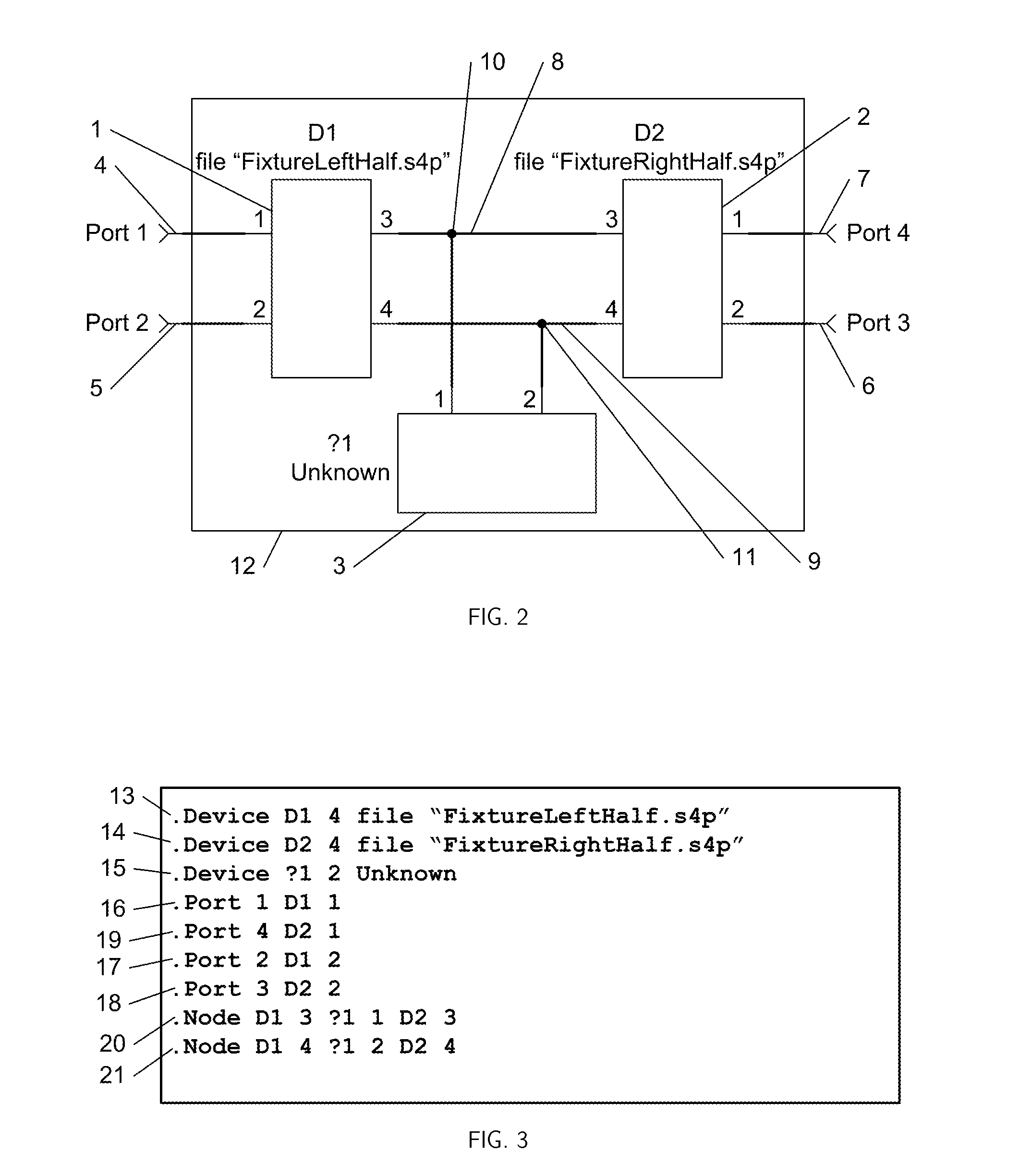
[0035]In accordance with the present invention, one is preferably provided with a system description and a set of known S-parameters measured at ports of this system. These various system descriptions are determined in a manner known to one of ordinary skill in the art, and may be provided in accordance with various known testing or mathematical model methods. In accordance with the invention, such a system description is considered to be an abstract term representing a description of a network. A network is comprised of devices, nodes, and system ports. A device is defined abstractly as a box with ports. Every device has a name, ports, and characteristics. A device's name is unique and serves to identify it within the network. The ports of the device are where signals enter and exit the device. The characteris...


PUM


Abstract

A method is provided for de-embedding measurements from a given network containing mixtures of devices with known and unknown S-parameters given a description of the network and the known S-parameters of the overall system.

Description

FIELD OF THE INVENTION[0001]The present invention relates in general to the measurement of characteristics of electronic networks and in particular to de-embedding measurements.BACKGROUND OF THE INVENTION[0002]In the field of measurement, it is useful to characterize devices. In this context, a device is defined as a network containing ports. The behavior of the device can be described as the relationship between signals on ports and how these signals are affected as they pass through the various ports of the device. The device that is being characterized is termed the device under test or DUT.[0003]As is known to those of ordinary skill in the art of high-speed electronics, a useful method of describing a system is through the provision of scattering parameters (S-parameters). As is known to those skilled in the art of microwave measurements, S-parameters define the port-to-port relationship of a network in the relationship Sa=b where S is a complex matrix that is provided for a va...

Claims


Application Information

Patent Timeline
Patent Type & Authority Patents(United States)
IPC IPC(8): G06F17/50G06F19/00G01R27/28
CPCG01R27/32G01R35/00
Inventor PUPALAIKIS, PETER J.DOSHI, KAVIYESH
Owner TELEDYNE LECROY
Learn More