
Laser tracker system and technique for antenna boresight alignment

a laser tracker and antenna boresight technology, applied in the field of alignment techniques, can solve the problems of difficult access to perform exterior alignment, difficult process, and ship-mounted antennas that do not lend themselves to antenna boresight, and achieve repeatable accurate data, simple and fast

Active Publication Date: 2013-10-29
RAYTHEON CO
View PDF8 Cites 3 Cited by
  • Summary
  • Abstract
  • Description
  • Claims
  • Application Information

AI Technical Summary

Benefits of technology

The patent describes a faster and easier way to align an antenna using a laser tracker and reference targets. By using multiple targets, the system can find the desired alignment more quickly. This technique is repeatable and accurate, and can be used for both initial and maintenance alignment checks. Overall, the patent provides a more efficient and effective way to align antennas using laser tracking technology.

Problems solved by technology

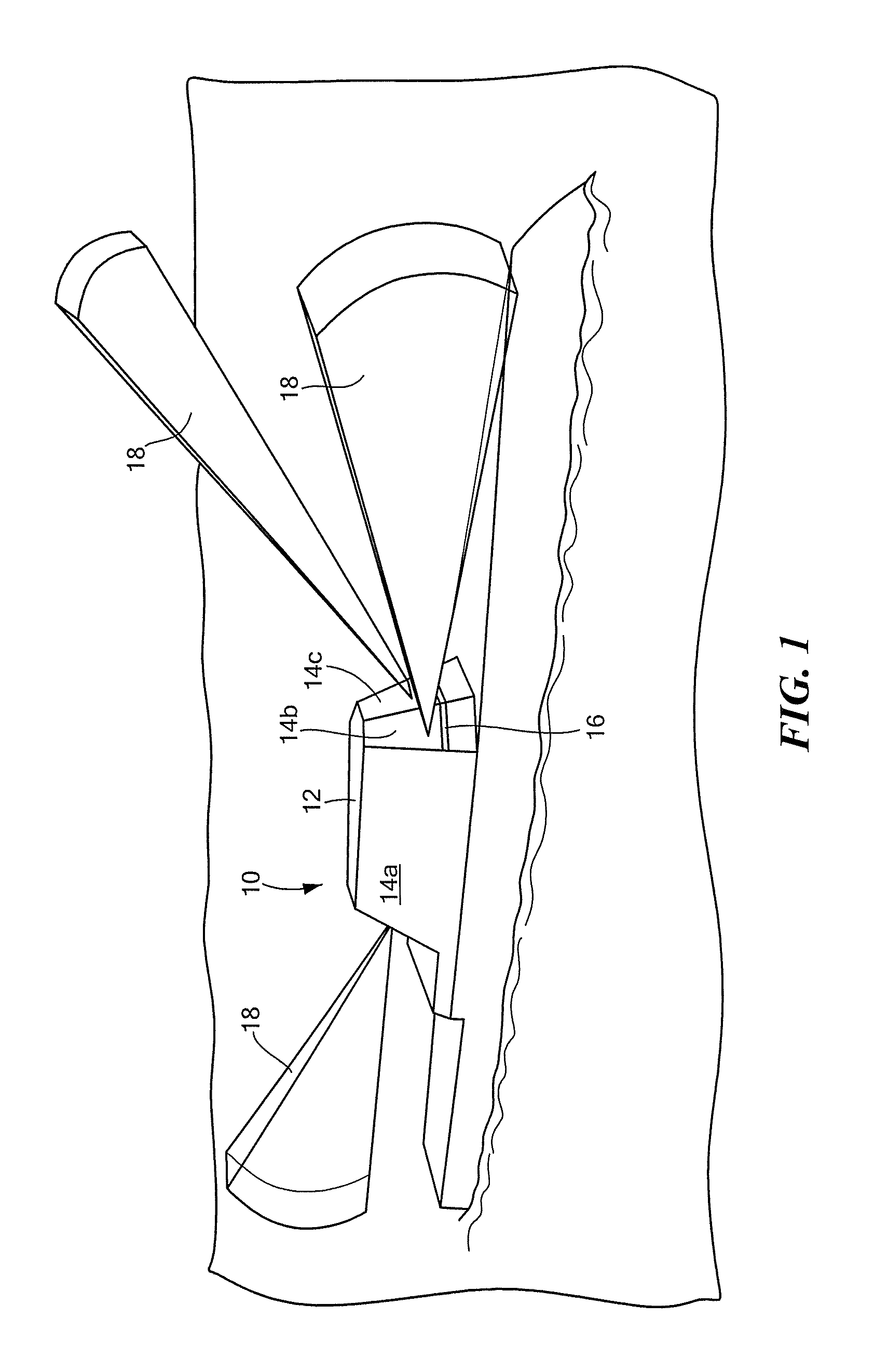
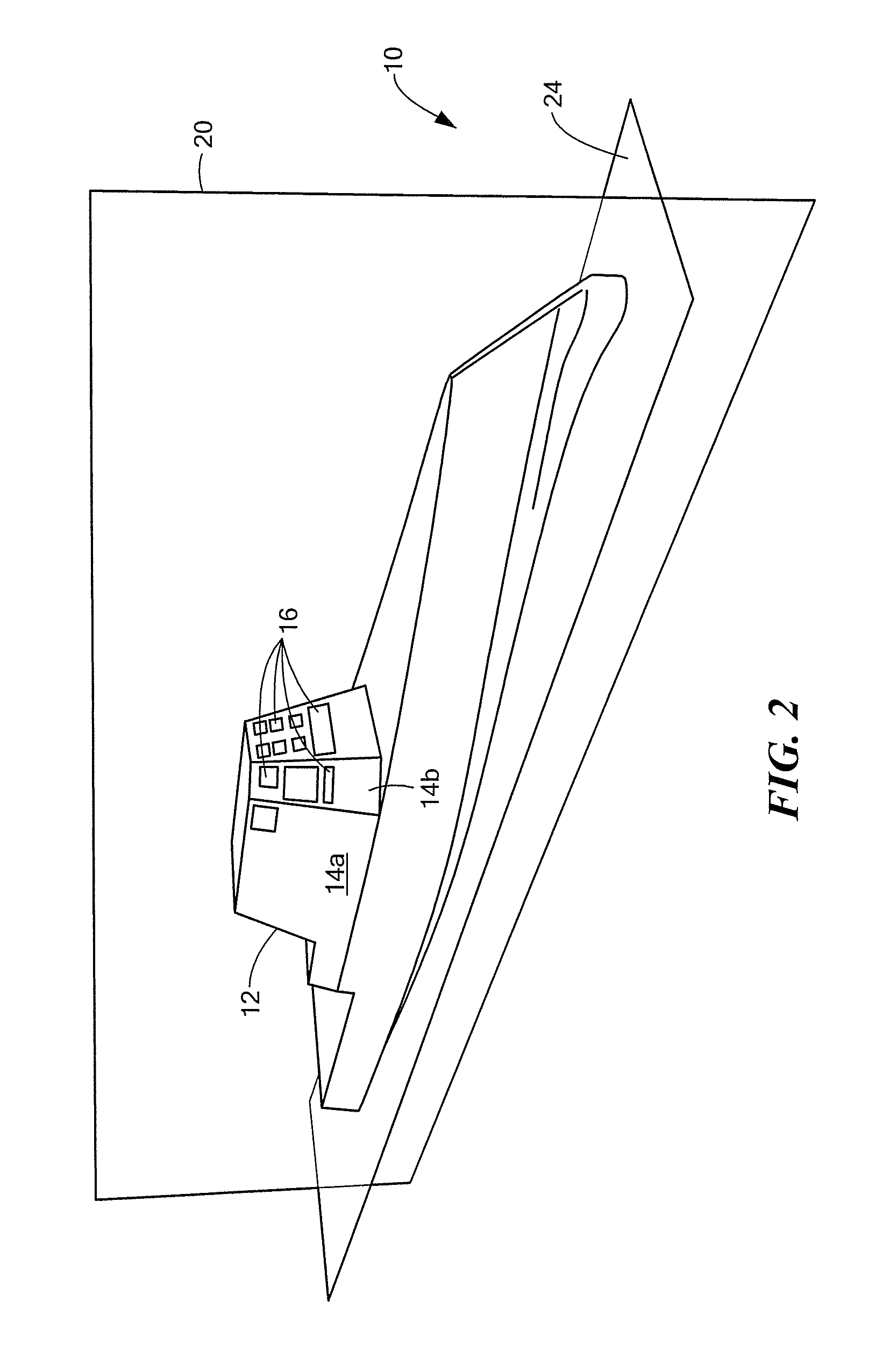
It has been recognized that some ship-mounted antenna do not lend themselves to antenna boresight using conventional alignment techniques using targets outside (i.e. exterior to) the deckhouse.
Ships in the so-called Zumwalt class of guided missile destroyers, for example, have a shape and materials which make access to perform exterior alignment very difficult.
This process was not practical due to lack of access to the IFF radome face and radar absorbing material which covers the deckhouse.
Thus, Zumwalt class ships have a requirement to perform antenna boresight alignment from inside the deckhouse since conventional alignment techniques using targets outside the deckhouse cannot be used for the Zumwalt ship / antenna configuration.

Method used


Image

  • Laser tracker system and technique for antenna boresight alignment
  • Laser tracker system and technique for antenna boresight alignment
  • Laser tracker system and technique for antenna boresight alignment

Examples


Embodiment Construction

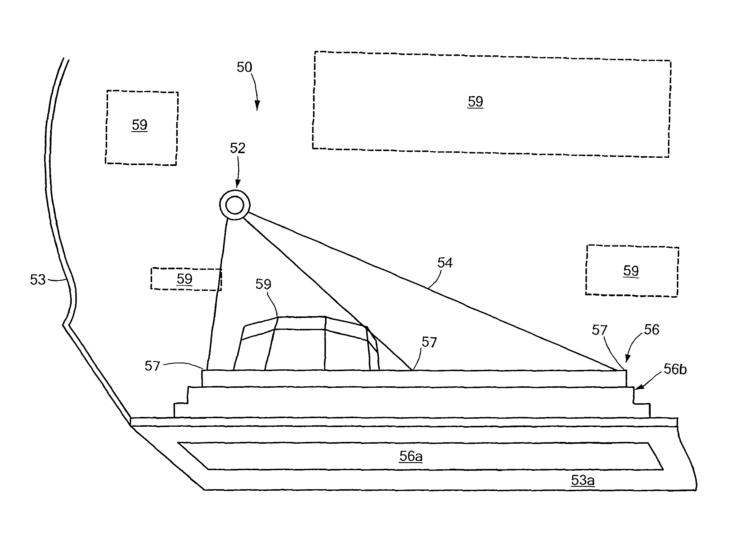
[0044]Before describing the details of a reliable and repeatable technique to perform an interior antenna boresight alignment, it should be appreciated that reference is sometimes made herein to the use of concepts, systems and techniques in the context of a particular environment (e.g. a ship and in particular antenna alignment from the interior of a ship deckhouse). Such references, however, are not intended as, and should not be construed as limiting. Rather such references are made solely to aid in providing clarity in the description of the concepts, systems and techniques describe herein.

[0045]Thus, described herein is an antenna alignment technique and related system are particularly appropriate for use when alignment must be done from a confined space such as an interior space of a structure on which the antenna is mounted. The alignment system and technique is also appropriate for use in an outdoor setting (i.e. the system and technique can be used in both indoor and outdoo...


PUM


Abstract

A system and processes for aligning an antenna boresight from a position which is internal to a structure on which the antenna is mounted is described. The system includes a laser tracking system and a plurality of targets disposed on a surface of the antenna.

Description

GOVERNMENT RIGHTS[0001]This invention was made with government support under Contract No. N00024-05-C-5346, awarded by the Department of the Navy. The government has certain rights in this invention.CROSS REFERENCE TO RELATED APPLICATIONS[0002]Not applicable.FIELD OF THE INVENTION[0003]The concepts, systems and techniques described herein relate generally to alignment techniques and more particularly to a method and apparatus for aligning a coordinate system of an antenna with a coordinate system of a platform on which the antenna is mounted.BACKGROUND OF THE INVENTION[0004]As is known in the art, modern ships often have antenna mounted on a deckhouse. The antenna boresight of ship-mounted antenna needs to be accurately aligned to the ship's Master Reference Coordinate System (MRCS). Antenna boresight alignment has traditionally been done from the ship exterior using optical targets and a theodolite.SUMMARY OF THE INVENTION[0005]In accordance with the present concepts, systems and t...

Claims


Application Information

Patent Timeline
Patent Type & Authority Patents(United States)
IPC IPC(8): G01B11/27G01B7/31
CPCH01Q3/005G01S17/88H01Q1/34H01Q21/08
Inventor WERNIG, MICHAEL C.IRWIN, DAVID J.ACORACI, JOSEPH H.
Owner RAYTHEON CO
Learn More