
Air supplier, particularly for an air supply system for fuel cells

a fuel cell and air supply technology, applied in the direction of positive displacement liquid engines, liquid fuel engines, piston pumps, etc., can solve the disadvantageous high space requirements of known designs, and achieve the effect of increasing the efficiency of air suppliers and achieving maximum possible flow retardation

Inactive Publication Date: 2013-10-29
DAIMLER AG
View PDF9 Cites 8 Cited by
  • Summary
  • Abstract
  • Description
  • Claims
  • Application Information

AI Technical Summary

Benefits of technology

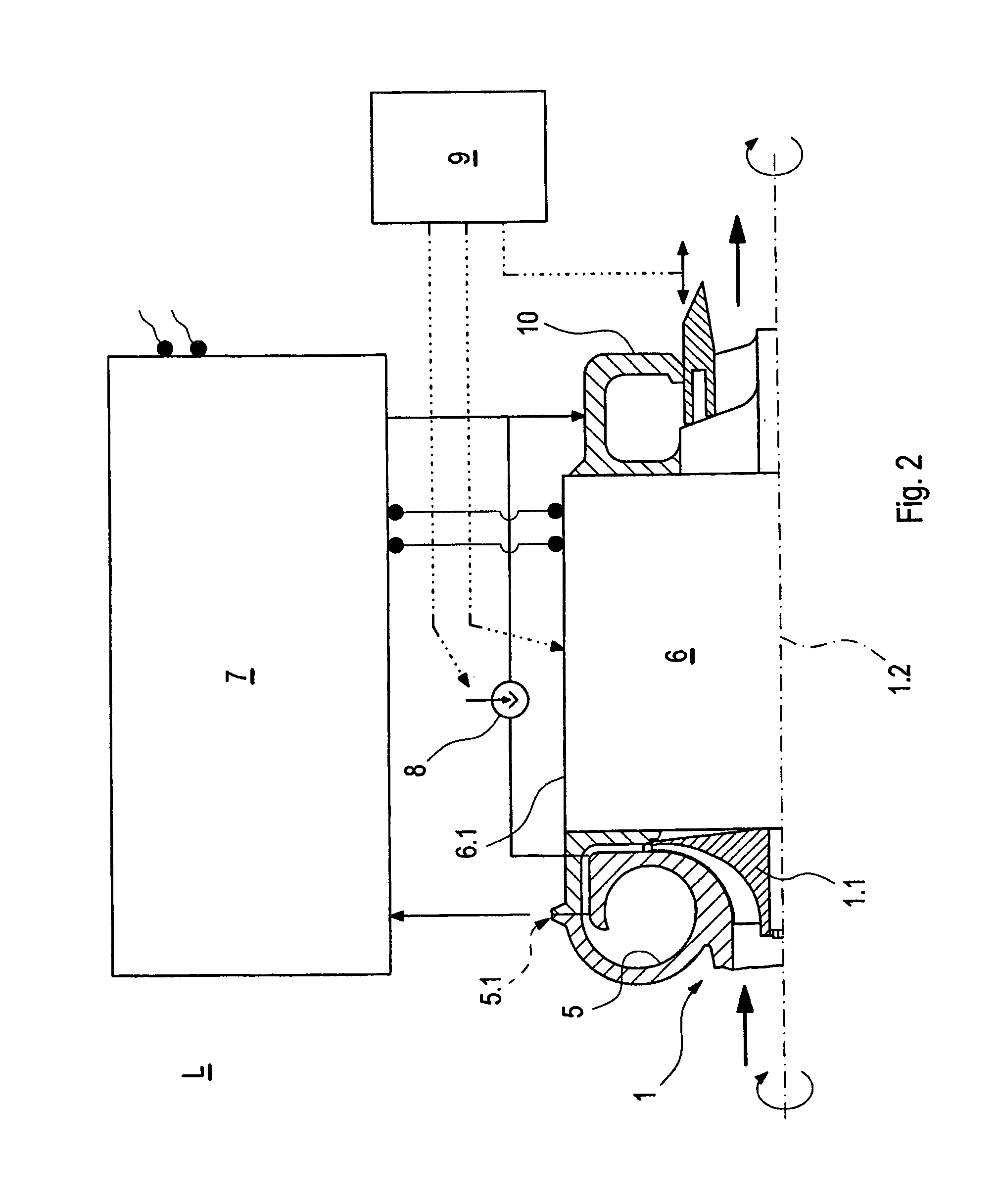
This patent describes a design for a compact air supplier. The arrangement includes a collection coil that extends radially inward, using the space between the axial annular chamber and the rotational axis. The compressor's outer diameter is not larger than the electric motor's outer diameter. A bladed axial diffuser or vane structure is placed in the axial annular chamber, which improves efficiency and optimizes flow retardation. This design allows for increased air supplier output and better air flow control.

Problems solved by technology

However, the high space requirement of the known design is disadvantageous in connection with the above-mentioned air supplier applications.

Method used


Image

  • Air supplier, particularly for an air supply system for fuel cells
  • Air supplier, particularly for an air supply system for fuel cells
  • Air supplier, particularly for an air supply system for fuel cells

Examples


Embodiment Construction

[0015]Corresponding parts are provided with the same reference numerals in all figures.

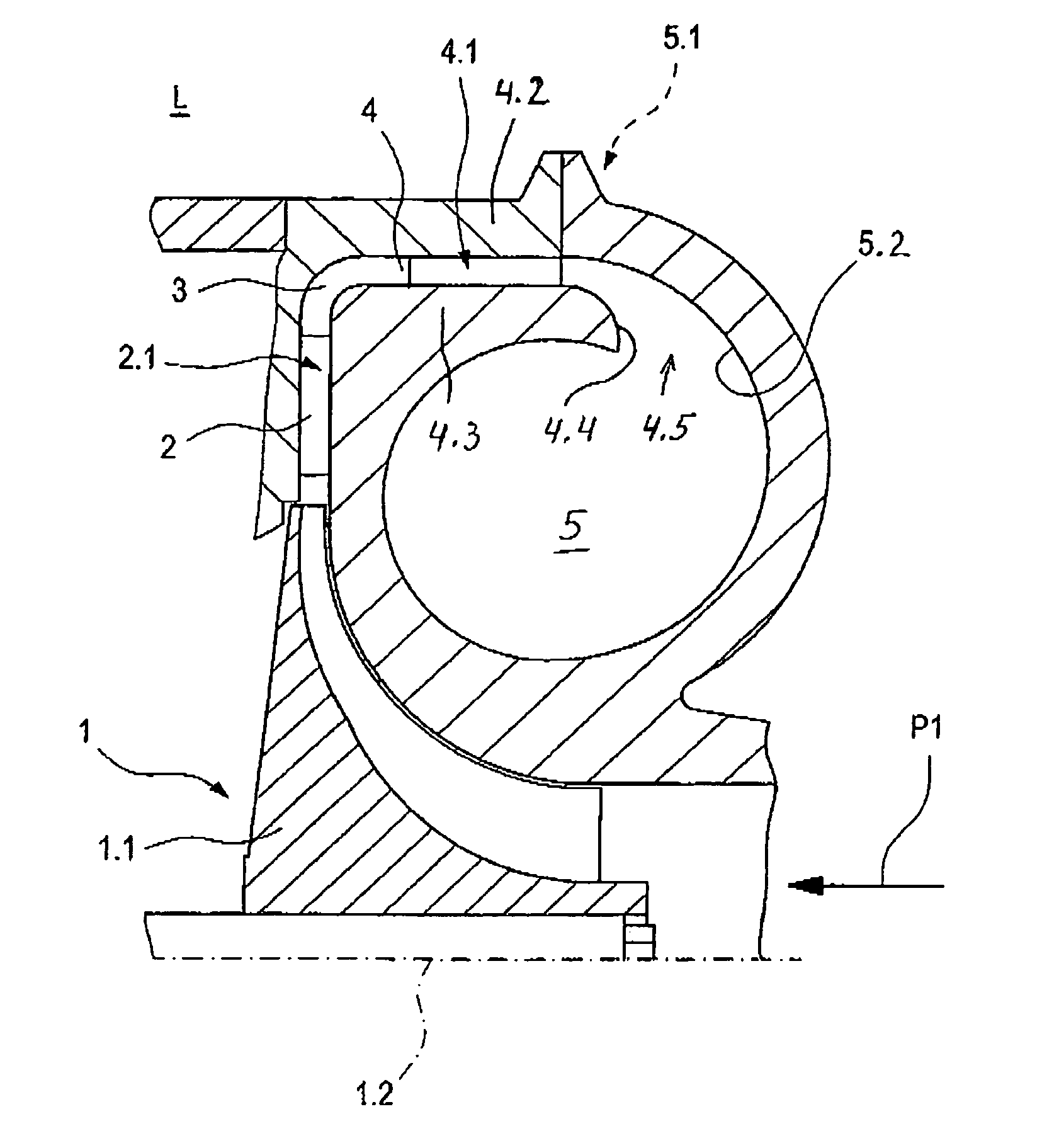
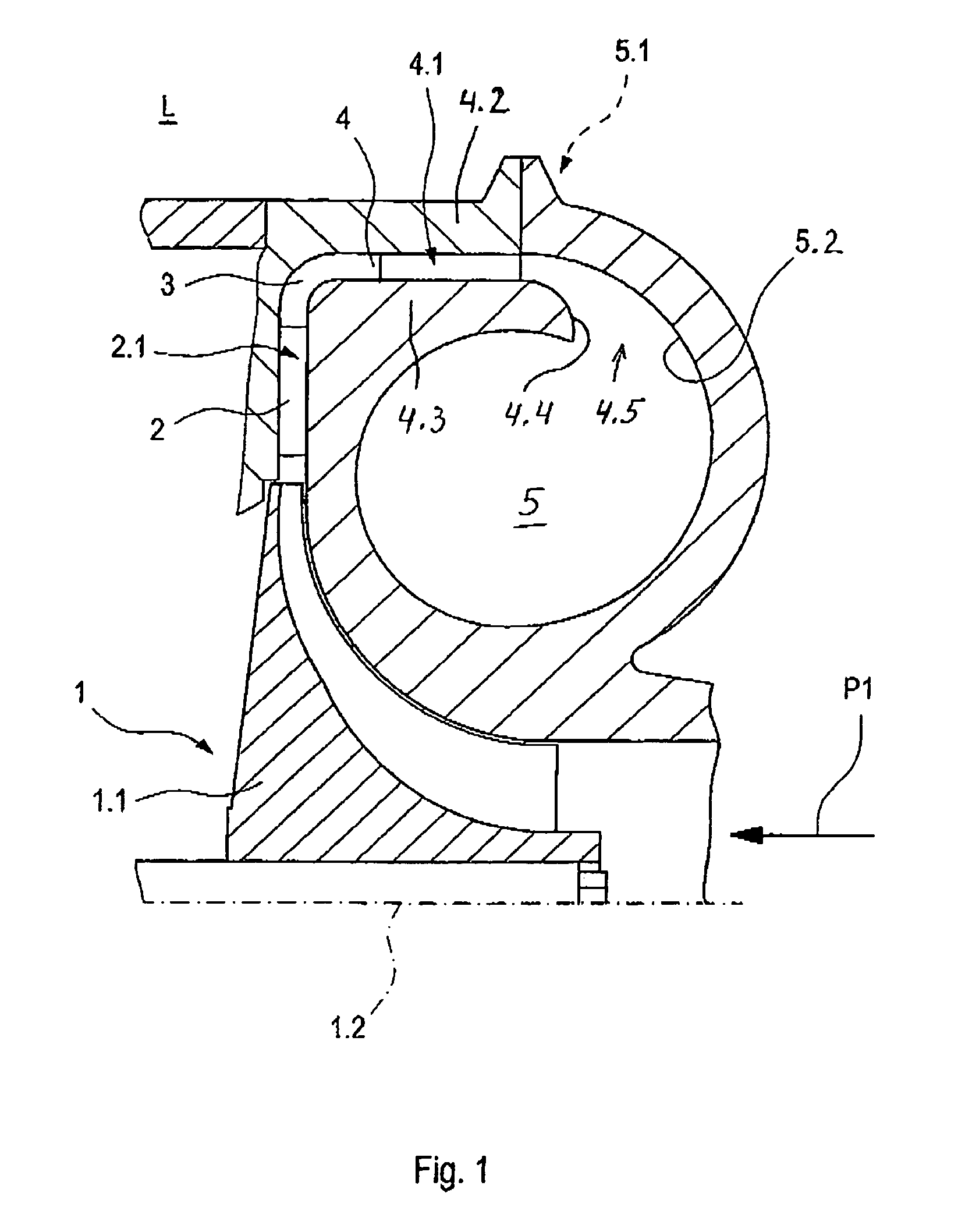
[0016]In the first sectional view of a first embodiment of an air supplier L according to the invention shown in FIG. 1, the essential elements of a compressor 1 are shown. The first section only shows one half of the air supplier L, specifically the upper half of the air supplier L extending above the longitudinal axis.

[0017]The compressor 1 comprises a compressor wheel 1.1, which is arranged rotatable around the longitudinal axis 1.2. A radial diffuser 2 is arranged in the radial direction outside the compressor wheel 1.1, which diffuser is formed by two parallel side surfaces. The radial diffuser 2 can be made adjustable in a variable manner by arranging one of the side surfaces in an adjustable manner.

[0018]The radial diffuser 2 extends to an axial annular channel 4 via a diverting channel section 3, which channel 4 again empties into a coil (also called collection space), which is formed so a...


PUM


Abstract

In an air supplier particularly for air supply systems for fuel cells including a compressor having a housing with a radial diffuser and including a rotor operated by an electric motor, a diverting channel is connected to the radial diffuser providing a communication path guiding the air via an axial annular channel to an inwardly extending collecting chamber via a final diffuser formed by a curved end section of a wall delimiting the annular passage and an inwardly curved wall area of the collection chamber, the compressor housing having an outer diameter is not substantially larger than the outer diameter of the electric motor.

Description

[0001]This is a Continuous-In-Part Application of pending international patent application PCT / EP2008 / 004461 filed Jun. 4, 2008 and claiming the priority of German patent application 10 2007 028 742.0 filed Jun. 21, 2007.BACKGROUND OF THE INVENTION[0002]The invention relates to an air supplier with a compressor having a radial diffuser, particularly for air supply systems of fuel cells operated by means of an electric motor or for exhaust gas turbochargers of internal combustion engines.[0003]Air suppliers of the above-mentioned type are known in the state of the art and serve for supplying air to fuel cells, in particular of a fuel cell stack. They include a compressor with a compressor wheel operated by an electric motor and a radial diffuser for increasing the air pressure.[0004]DE 1 628 280 discloses such an air supplier with a compressor in the form of an axial compressor.[0005]However, the high space requirement of the known design is disadvantageous in connection with the abo...

Claims


Application Information

Patent Timeline
Patent Type & Authority Patents(United States)
IPC IPC(8): F02B33/44F02B33/00F04D29/44F04D29/54
CPCF04D25/06F04D29/4233F04D29/441F04D29/444
Inventor SUMSER, SIEGFRIEDSTUTE, MANFREDLOFFLER, PAUL
Owner DAIMLER AG
Learn More