
Internal combustion engine

a combustion engine and internal combustion technology, applied in the direction of machines/engines, liquid fuel feeders, mechanical equipment, etc., can solve the problems of reducing deteriorating the combustion of the internal combustion engine, and reducing the combustion temperature, so as to avoid the reduction of the freedom degree of the engine room layout. , the effect of large heat capacity

Active Publication Date: 2013-10-29
HONDA MOTOR CO LTD
View PDF14 Cites 0 Cited by
  • Summary
  • Abstract
  • Description
  • Claims
  • Application Information

AI Technical Summary

Benefits of technology

[0005]In the configuration where the EGR pipe is disposed so as to pass beside the cylinder row end of the engine body, the exhaust gas recirculating passage becomes longer, and thus the temperature decrease of the exhaust gas passing through the exhaust gas recirculating passage (EGR gas) becomes greater, which leads to decrease in combustion temperature, thereby deteriorating combustion of the internal combustion engine.
[0006]In the configuration where the EGR pipe passes over the cylinder head cover, compared with the configuration where the EGR pipe passes beside the cylinder row end of the engine body, the length of the exhaust gas recirculating passage can be configured to be shorter, thereby preventing decrease in the temperature of the EGR gas passing through the exhaust gas recirculating passage.
[0007]In this configuration, however, since there are many plastic members with low heat resistance disposed on the cylinder cover such as air cleaner and intake tube, when the EGR pipe gets heated, these members disposed on the cylinder head cover will be exposed to the heat of the exhaust gas passing the EGR pipe, and thus their durability and performance will deteriorate. Therefore, members disposed near the EGR pipe will be damaged by heat. In addition, this configuration requires a space for disposing EGR pipe, thereby limiting the freedom degree of the layout of the frontal part of the vehicle.

Problems solved by technology

In the configuration where the EGR pipe is disposed so as to pass beside the cylinder row end of the engine body, the exhaust gas recirculating passage becomes longer, and thus the temperature decrease of the exhaust gas passing through the exhaust gas recirculating passage (EGR gas) becomes greater, which leads to decrease in combustion temperature, thereby deteriorating combustion of the internal combustion engine.
In this configuration, however, since there are many plastic members with low heat resistance disposed on the cylinder cover such as air cleaner and intake tube, when the EGR pipe gets heated, these members disposed on the cylinder head cover will be exposed to the heat of the exhaust gas passing the EGR pipe, and thus their durability and performance will deteriorate.
Therefore, members disposed near the EGR pipe will be damaged by heat.
In addition, this configuration requires a space for disposing EGR pipe, thereby limiting the freedom degree of the layout of the frontal part of the vehicle.
On the other hand, if the main part of the exhaust gas recirculating passage is an internal passage passing through the cylinder head from the intake side to the exhaust side, the length of the exhaust gas recirculating passage can be configured to be shorter, however, during cold start-warm up process there is a risk that the EGR gas may be excessively cooled by the cylinder head which is cooled and has a large heat capacity.
This will lead to decrease in combustion temperature, thereby deteriorating combustion quality of the internal combustion engine.

Method used


Image

  • Internal combustion engine
  • Internal combustion engine
  • Internal combustion engine

Examples


Embodiment Construction

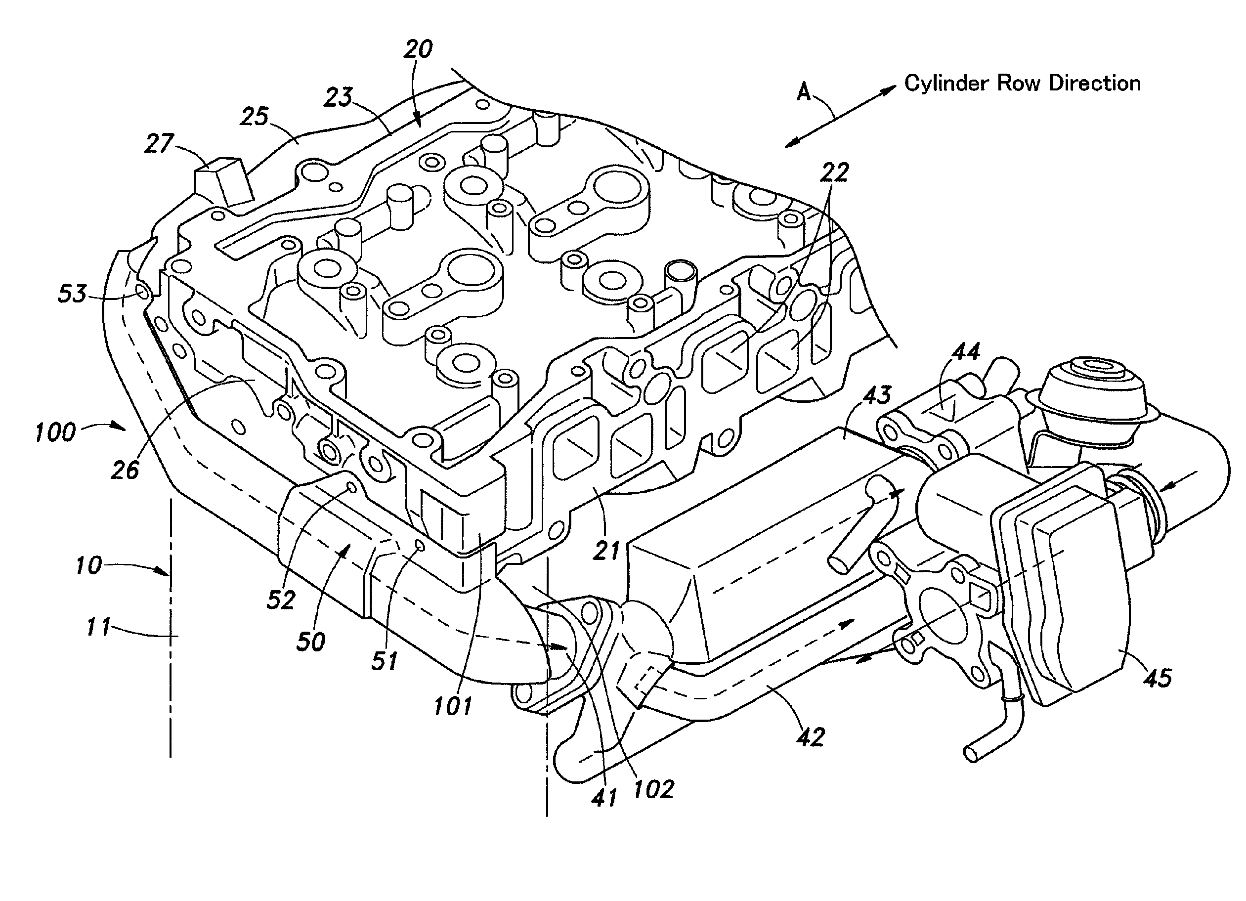
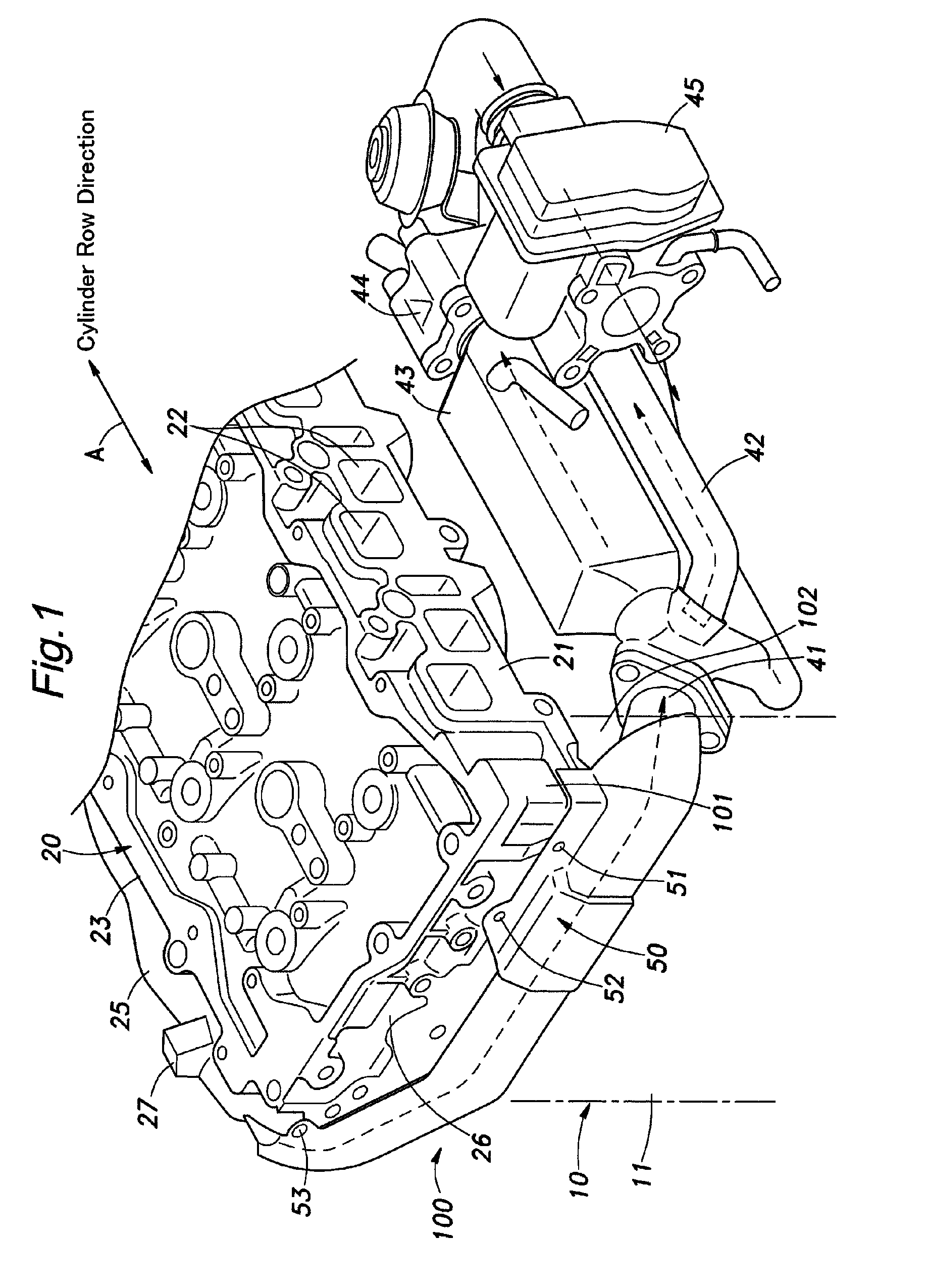
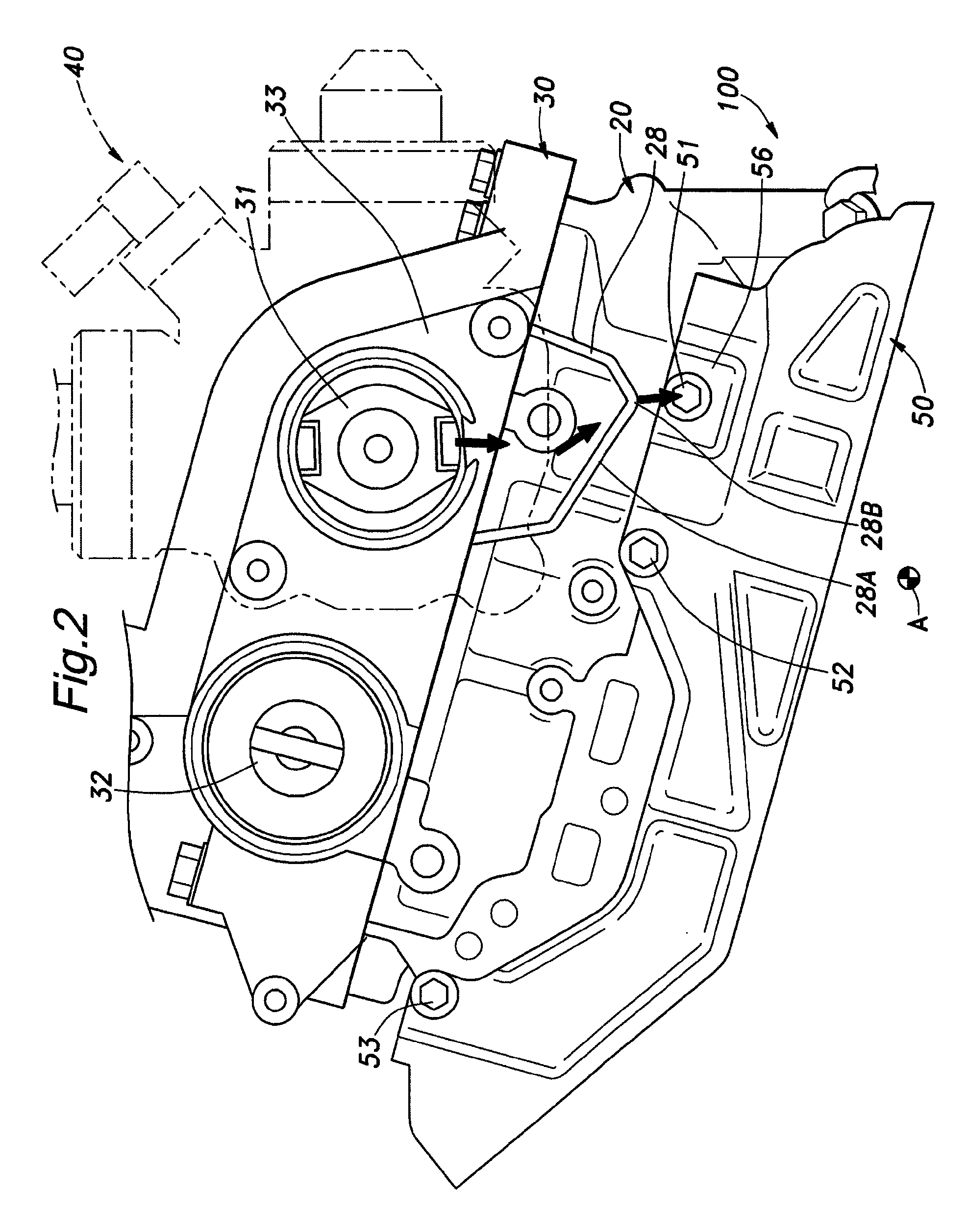
[0026]Next, an embodiment of the internal combustion engine according to the present invention is described with a reference of FIGS. 1-4.

[0027]An engine body 100 comprises a cylinder block 10, a cylinder head 20 mounted on the cylinder block 10, and a cam holder 30 mounted on the cylinder head 20.

[0028]The cylinder block 10 has a plurality of cylinder bores (not shown) formed therein, and defines a plurality of cylinders arranged in one line along with the cylinder head 20 which covers the cylinder block 10. The row direction of the plurality of cylinders is represented by an arrow A in these figures.

[0029]The cylinder head 20 has intake ports 22 for the cylinders formed on an intake side 21 of the engine body defined on one side of the engine body with respect to the cylinder row direction A. The cylinder head 20 also has exhaust ports (not shown) for the cylinders formed on an exhaust side 23 of the engine body defined on the other side of the engine body with respect to the cyli...


PUM


Abstract

The present invention provides an internal combustion engine comprising an engine body 100, an overhang 101 projecting from a cylinder row end the engine body 100 and extending from an intake side 21 to an exhaust side 23 of the engine body, and an EGR pipe 41 disposed in a space 102 defined under the overhang 101 with a gap 103 between the EGR pipe 41 and the cylinder row end of the engine body, thereby avoiding the excessive cooling of EGR gas passing through the EGR pipe 41 while reducing a length of a passage defined by the EGR pipe 41, and preventing members disposed near the EGR pipe 41 from being damaged by heat.

Description

TECHNICAL FIELD[0001]The present invention relates to an internal combustion engine, and in particular to a layout and surrounding structure of an exhaust gas recirculating passage member of an internal combustion engine for recirculating exhaust gas.BACKGROUND OF THE INVENTION[0002]An internal combustion engine used for automobiles generally comprises a plurality of cylinders defined in an engine body which consists of a cylinder block and a cylinder head, an intake manifold or an intake air passage member provided on an intake side of the engine body defined on one side of the engine body with respect to a cylinder row direction, and an exhaust manifold or an exhaust air passage member provided on an exhaust side of the engine body with respect to the cylinder row direction.[0003]In order to improve the exhaust gas performance, internal combustion engines which conduct exhaust gas recirculation (EGR) are provided with exhaust gas recirculating passage members for recirculating the...

Claims


Application Information

Patent Timeline
Patent Type & Authority Patents(United States)
IPC IPC(8): F02B47/08F02M25/07F01N13/14
CPCF02B77/11F02M25/0703F02M25/0714F02M25/0721F02M25/0726F02M25/0747Y02T10/121F02M26/12F02M26/18F02M26/11F02M26/22F02M26/41
Inventor SHIMOYAMA, KAZUAKITSUKAHARA, KENJIMATSUI, KAZUHIRO
Owner HONDA MOTOR CO LTD
Learn More