Blowout preventers using plates propelled by explosive charges

a technology of explosive charge and blowout preventer, which is applied in the direction of sealing/packing, pressure relieving device on the sealing face, borehole/well accessories, etc., can solve the problems of unreliable current blowout preventer, unreliable blowout preventer, etc., to prevent economic loss, prevent environmental damage, and prevent economic loss

Active Publication Date: 2013-10-29
MILANOVICH INVESTMENTS L L C
View PDF19 Cites 10 Cited by
  • Summary
  • Abstract
  • Description
  • Claims
  • Application Information

AI Technical Summary

Benefits of technology

[0024]Accordingly, it is a first object of the invention to prevent damage to the environment from oil well blowouts.
[0025]It is a second object of the invention to prevent economic loss from oil well blowouts.
[0026]It is a third object of the invention to prevent damage to the environment from any kind of fluid escaping from a pipe.
[0027]It is a fourth object of the invention is to prevent economic loss from any kind of fluid escaping from a pipe.
[0028]It is a fifth object of the invention to create a safer environment for any fluid carrying pipe or pipe-like structure.
[0029]It is a sixth object of the invention to provide a shutoff mechanism that can be reopened.

Problems solved by technology

As shown by recent events in the Gulf of Mexico, oil well blowouts are a serious threat to the environment, and can be very costly.
Current blowout preventers can be unreliable.
U.S. Pat. No. 4,619,284, issued on Oct. 28, 1986, to Jean-Jacques Delarue and Claude Ego, discloses a pyrotechnic valve that may either close an initially open pipe or open an initially closed pipe, but does not disclose its use in a blowout preventer.

Method used


Image

  • Blowout preventers using plates propelled by explosive charges
  • Blowout preventers using plates propelled by explosive charges
  • Blowout preventers using plates propelled by explosive charges

Examples


Embodiment Construction

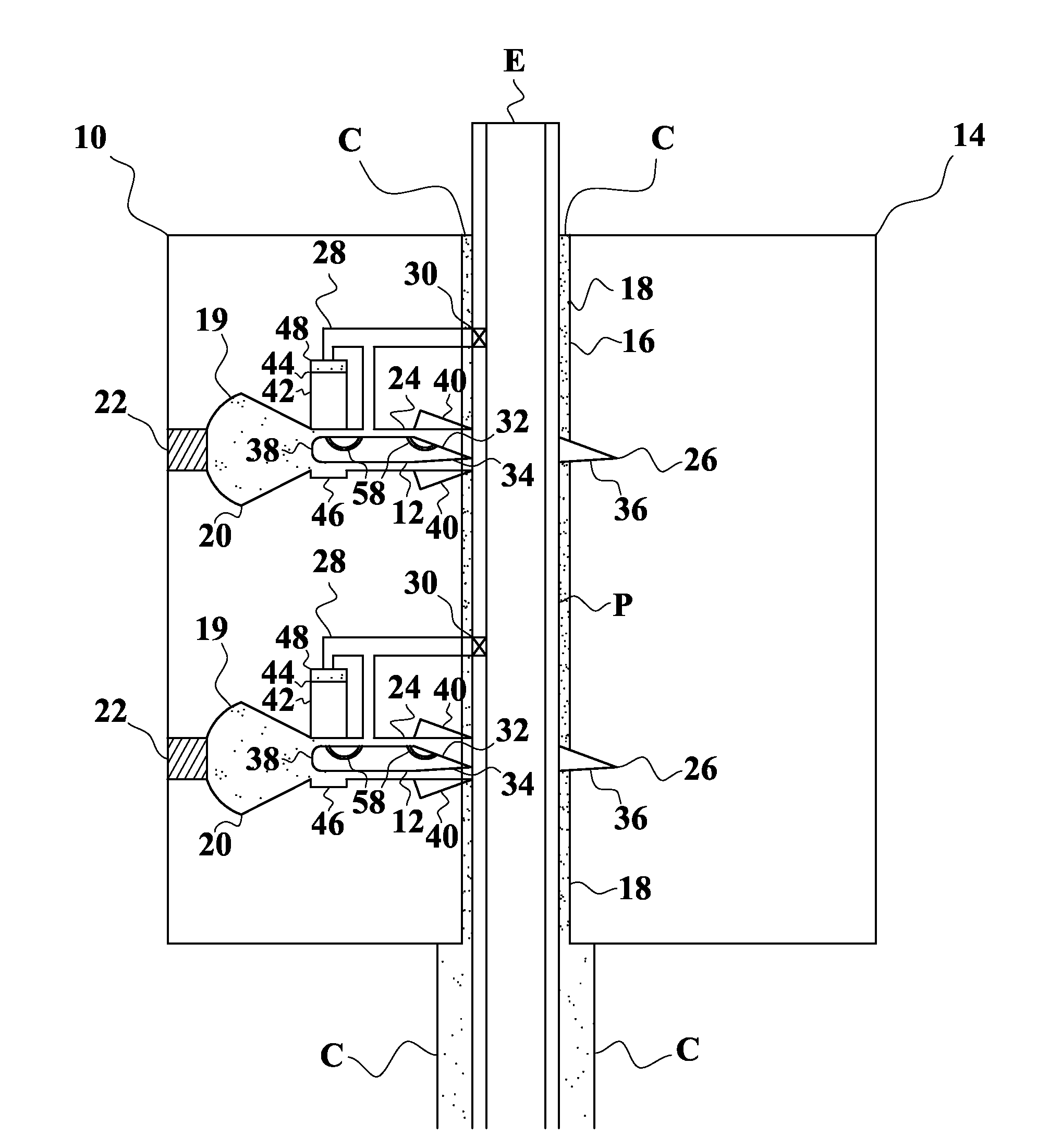
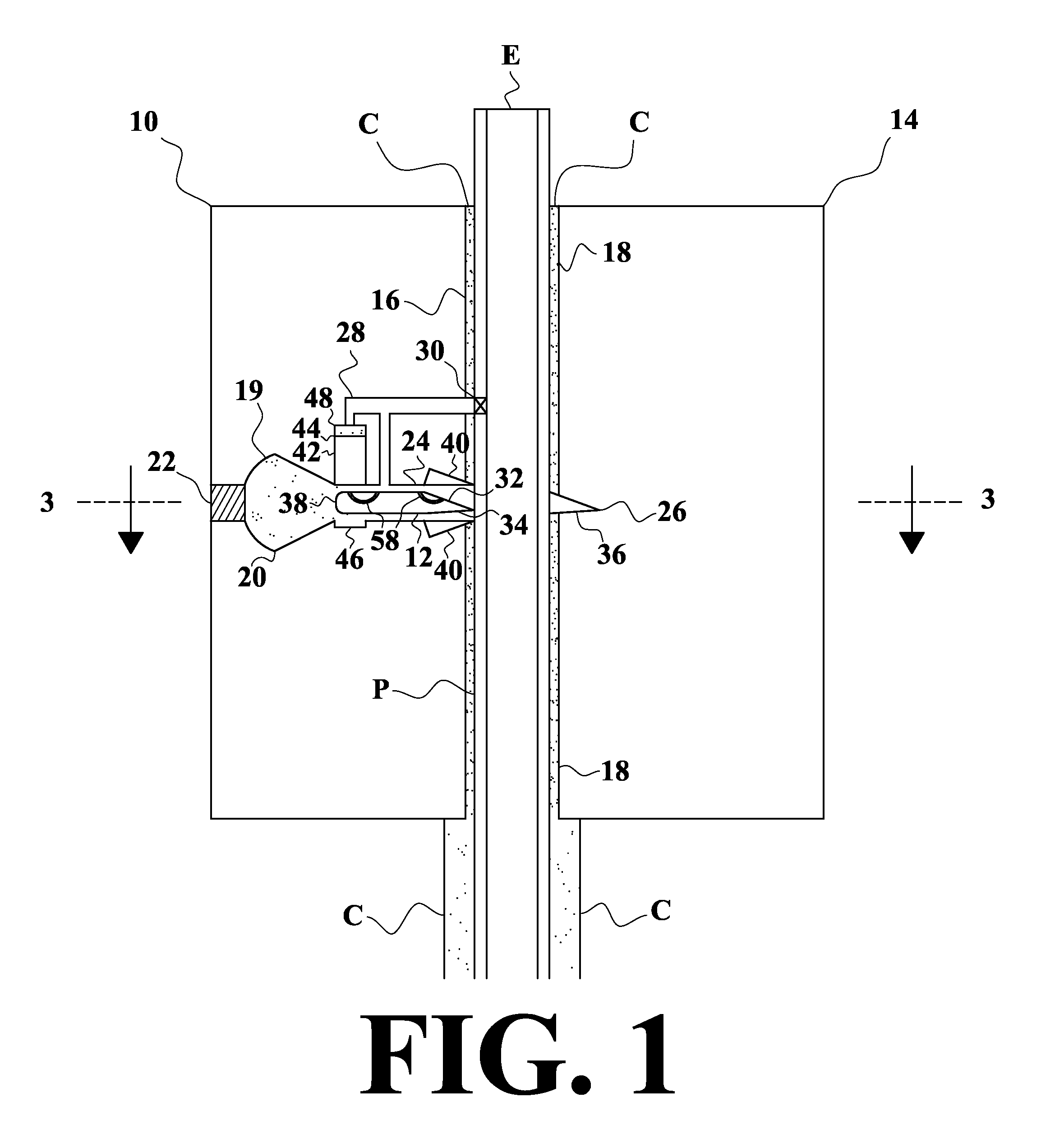
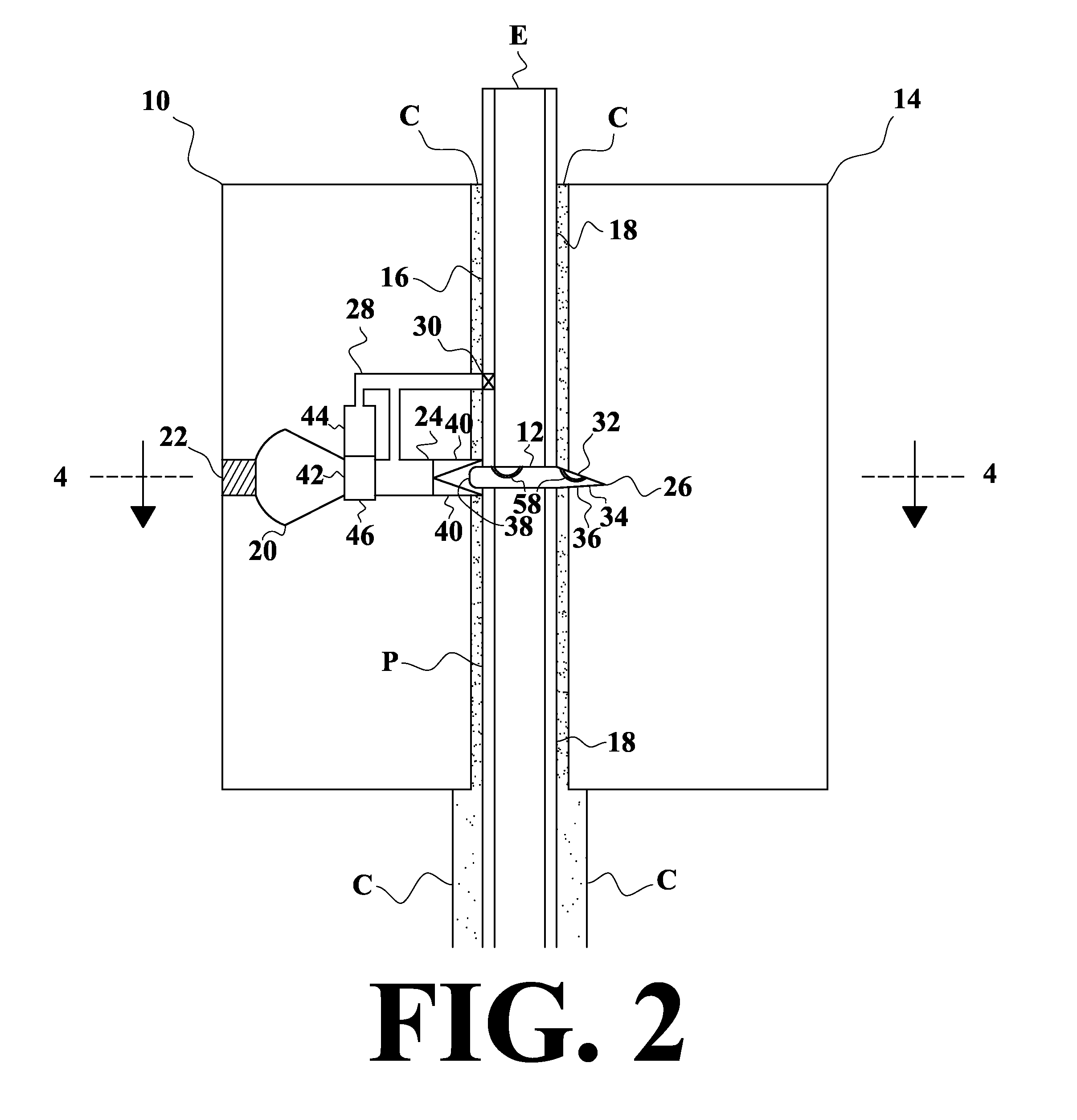
[0045]The present invention a blowout preventer with one or more explosively actuated plates.

[0046]FIG. 1 is a vertical sectional view drawn along lines 1-1 of FIG. 3 of the first preferred embodiment of the invention 10, showing the position of the plate 12 before the explosive charge has been fired. The block 14 has a cylindrical channel 16 with ends 18 configured so that it can be inserted over the open end E of pipe P through which fluid (such as petroleum or natural gas) can escape. (The pipe may be a well pipe or riser, undersea or on land.) An explosive charge 19 in chamber 20 when fired will propel the plate across the channel to block the flow of fluid. A receiver / ignitor 22 when ignite the explosive charge when it receives a radio, electrical, sonic or other signal to do so. When the charge is fired, the plate will move in passage 24 with far end 26. Vents 28 will allow gases from the charge to escape through one-way valves 30 into the pipe above the plate. The upper edge ...


PUM


Abstract

Blowout preventer blocks, each having a channel and plate(s) to close it. The blocks are placed over a pipe through which oil or other fluid is escaping, so that the pipe is in their channels. Alongside the channel in each block are one or more plates, having diameters somewhat larger than the diameter of the channel. Explosive charges propel the plates into the channel to seal it off and stop the leak. When multiple blocks and/or multiple plates in a block are placed over a pipe, the assembly may be referred to as a “Christmas tree.” There are passages that allow the plates to move into place to block the channel. Leading edges of the plates act as male elements that engage female reciprocal ends of the passages to create a seal. Grooves and tunnels in the plates allow fluid to escape into the pipe to ensure a seal.

Description

CROSS REFERENCE TO RELATED APPLICATION[0001]This application is a Continuation-In-Part of Regular Utility patent application Ser. No. 12 / 972,451, filed Dec. 18, 2010, which is incorporated herein by reference.BACKGROUND OF THE INVENTION[0002]1. Field of the Invention[0003]The present invention relates to apparatus and methods for preventing the escape of fluid from wells or pipes.[0004]2. Description of the Prior Art[0005]As shown by recent events in the Gulf of Mexico, oil well blowouts are a serious threat to the environment, and can be very costly. Current blowout preventers can be unreliable. While there are numerous prior inventions of blowout preventers, none are equivalent to the present invention.[0006]U.S. Pat. No. 1,543,456, issued on Jun. 23, 1925, to Robert Stirling, discloses an early blowout preventer, without the explosive charges of the instant invention.[0007]U.S. Pat. No. 3,548,848, issued on Dec. 22, 1970, to Gerhardt C. Stichling, discloses explosive actuated val...

Claims


Application Information

Patent Timeline
Patent Type & Authority Patents(United States)
IPC IPC(8): E21B43/11F16K17/14
CPCE21B33/061E21B43/116Y10T137/1647
Inventor MILANOVICH, PHILIP JOHN
Owner MILANOVICH INVESTMENTS L L C
Why Eureka
Try Eureka