Grid and rotatable cube guide localization fixture for biopsy device

a biopsy device and guide fixture technology, applied in the field of biopsy devices, can solve the problem of too much overlap of holes in the biopsy instrument, and achieve the effect of guiding the biopsy instrumen

Inactive Publication Date: 2013-10-29
DEVICOR MEDICAL PROD
View PDF36 Cites 15 Cited by
  • Summary
  • Abstract
  • Description
  • Claims
  • Application Information

AI Technical Summary

Benefits of technology

[0010]The present invention addresses these and other problems of the prior art by providing an apparatus for locating a breast of a patient and guiding a biopsy instrument cannula for insertion into tissue, wherein one of two compression surfaces that are positioned relative to a patient support surface to opposingly compress the patient's breast, is a grid plate having a plurality of grid apertures. The orientation of guide holes formed in the guide cube enhance options for positioning the guide cube to closely position an insertion point.
[0011]In one aspect of the invention, a guide device, with guide holes passing transversely to one another between differing pairs of opposing faces, is inserted into a selected one of the guide apertures. A grounding structure between the guide device and the grid plate prevents the guide cube from passing out of a distal side of the grid plate presented against the patient. Thereby, an intuitive approach to guiding a biopsy instrument by placing a guide cube is enhanced by providing multiple faces of the device that may contain centered or off center guide holes. Placing a pair of closely positioned guide holes on the same face may otherwise not effectively guide the biopsy instrument with too much hole overlap. Portions of the biopsy instrument that are not in contact with the guide hole increase force in other areas that may lead to bending or fracture.
[0013]In yet another aspect of the invention, an intermediary device of a rotating guide is received over a biopsy instrument, which in turn is received into an enlarged guide hole in a guide cube inserted into the grid plate. The rotating guide thus may serve purposes such as presenting a circular transverse cross section to allow rotation of a nonround biopsy instrument cannula. To give a number of hole positions within a selected grid aperture, a set of guide cubes are presented as a set, each with various unique positions of one or more guide holes. Selecting a guide cube thus gives enhanced flexibility in positioning the insertion point.

Problems solved by technology

Placing a pair of closely positioned guide holes on the same face may otherwise not effectively guide the biopsy instrument with too much hole overlap.
Portions of the biopsy instrument that are not in contact with the guide hole increase force in other areas that may lead to bending or fracture.

Method used


Image

  • Grid and rotatable cube guide localization fixture for biopsy device
  • Grid and rotatable cube guide localization fixture for biopsy device
  • Grid and rotatable cube guide localization fixture for biopsy device

Examples


Embodiment Construction

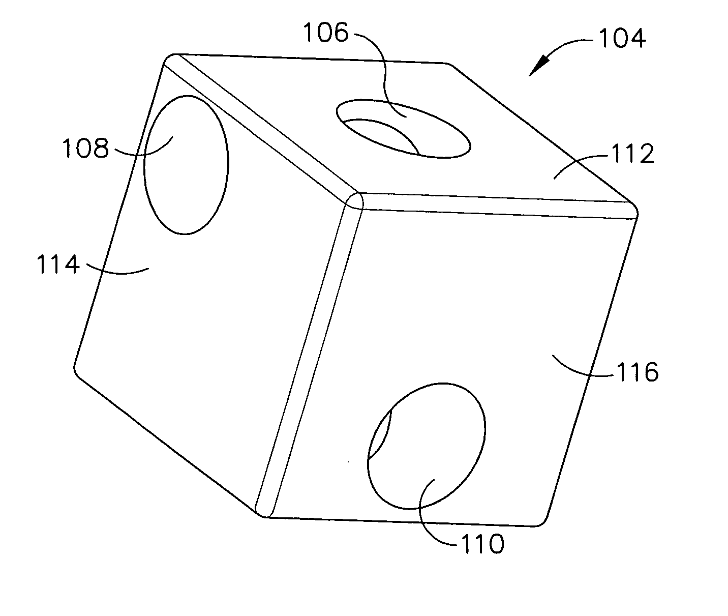
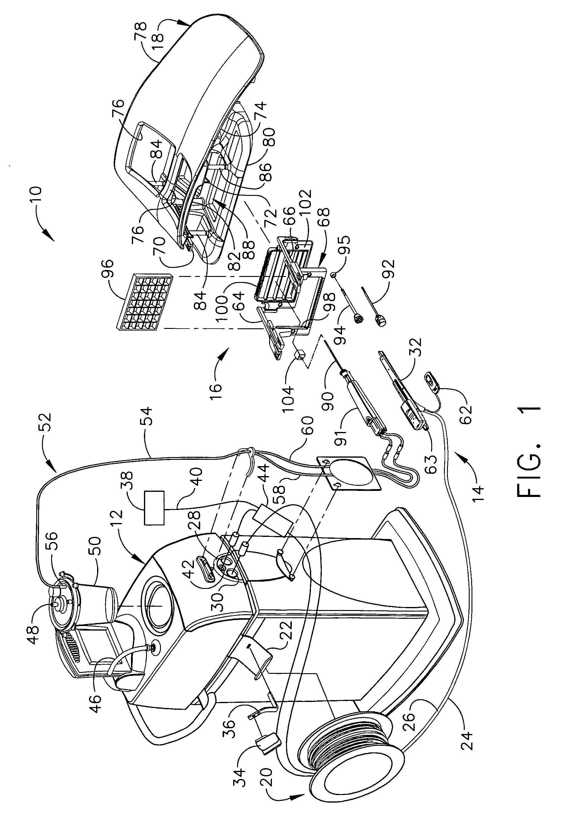
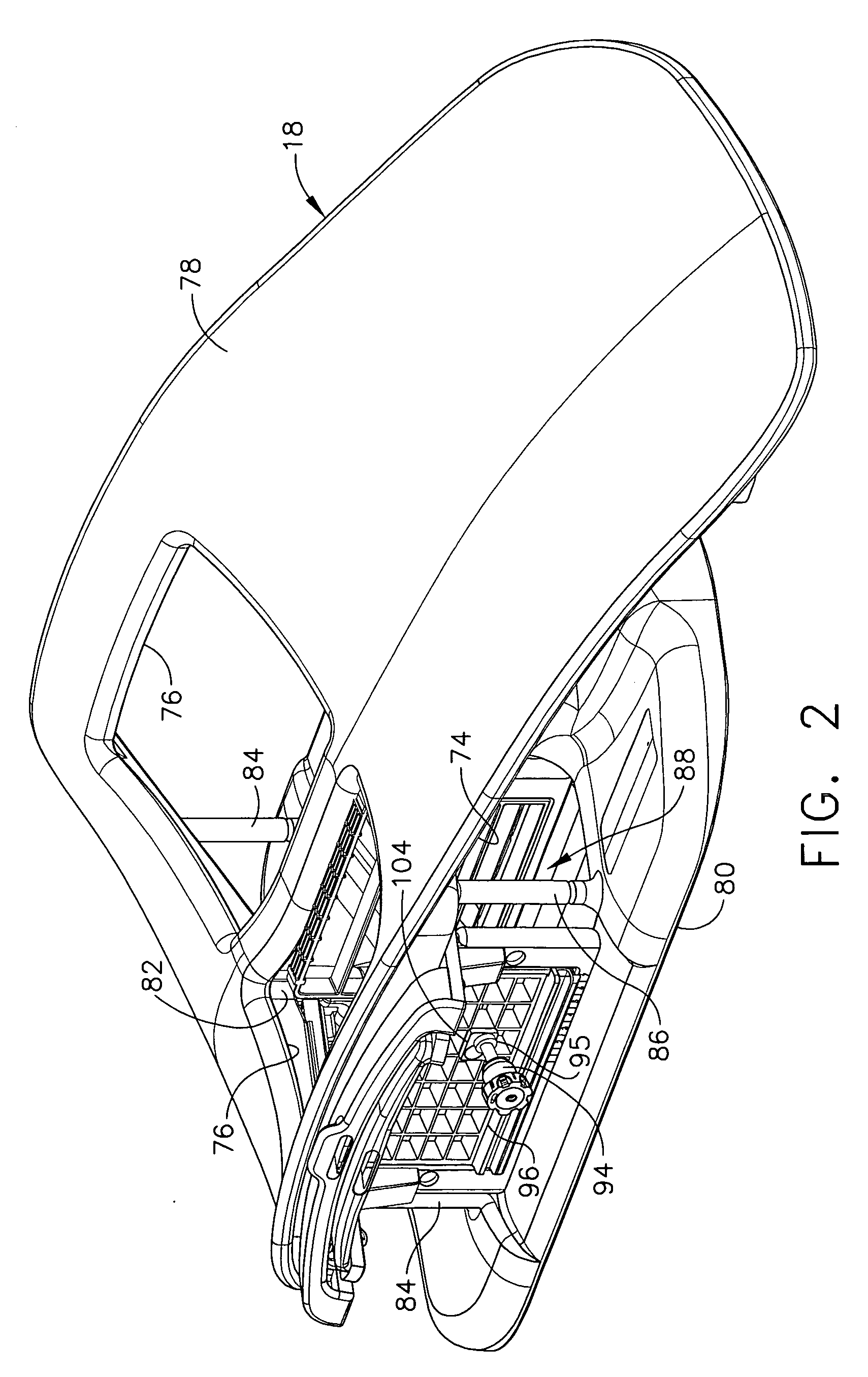
[0049]Turning to the Drawings, wherein like numerals denote like components throughout the several views, in FIGS. 1-3, a Magnetic Resonance Imaging (MRI) compatible biopsy system 10 has a control module 12 that typically is placed outside of a shielded room containing an MRI machine (not shown) or at least spaced away to mitigate detrimental interaction with its strong magnetic field and / or sensitive radio frequency (RF) signal detection antennas. As described in U.S. Pat. No. 6,752,768, which is hereby incorporated by reference in its entirety, a range of preprogrammed functionality is incorporated into the control module 12 to assist in taking these tissue samples. The control module 12 controls and powers an MRI biopsy device 14 that is positioned and guided by a localization fixture 16 attached to a breast coil 18 that is placed upon a gantry (not shown) of the MRI machine.

[0050]The control module 12 is mechanically, electrically, and pneumatically coupled to the MRI biopsy dev...


PUM


Abstract

A biopsy system with a grid plate used as either a lateral or medial compression plate of a localization fixture used with a breast coil includes a rotatable guide cube that may be inserted into a desired rectangular recess in the grid plate after rotating to position a selected guide hole in the desired spatial orientation. Versions of a guide cube include those rotatable in two axes to provide additional hole positions, angled holes, enlarged circular holes that function with a rotating guide to support a noncircular biopsy instrument cannula (e.g., trocar / sleeve combination, core biopsy probe of a biopsy device) for rotation. A rotating guide may have an unlocked state for easily sliding to a selected longitudinal position thereon. Thereafter, the rotating guide is locked to serve as a positive depth stop (e.g., quarter turn locking elastomeric rings, triangular and scissor clips, and shutter depth stops).

Description

CROSS REFERENCE TO RELATED APPLICATIONS[0001]The present application is related to the co-pending and commonly-owned U.S. patent application Ser. No. 11 / 414,988, “BIOPSY CANNULA ADJUSTABLE DEPTH STOP” to Hibner et al., filed on even date herewith, the disclosure of which is hereby incorporated by reference in its entirety.FIELD OF THE INVENTION[0002]The present invention relates in general to biopsy devices, and more particularly to biopsy devices having a cutter for severing tissue, and even more particularly to a localization and guidance fixture that guides insertion of a probe, or a sleeve that subsequently receives the probe of a biopsy device.BACKGROUND OF THE INVENTION[0003]When a suspicious tissue mass is discovered in a patient's breast through examination, ultrasound, MRI, X-ray imaging or the like, it is often necessary to perform a biopsy procedure to remove one or more samples of that tissue in order to determine whether the mass contains cancerous cells. A biopsy may b...

Claims


Application Information

Patent Timeline
Patent Type & Authority Patents(United States)
IPC IPC(8): A61B10/00A61B19/00
CPCA61B17/3403A61B10/0266A61B10/0233A61B19/201A61B2017/3411A61B2019/205A61B90/11A61B90/17
Inventor HIBNER, JOHN A.AVIMUKTA, KREENASHANNON, KEVIN R.
Owner DEVICOR MEDICAL PROD
Why Eureka
Try Eureka