
Configurable multi-axis electric drive system concept

a multi-axis, electric drive technology, applied in the direction of motor/generator/converter stopper, dynamo-electric converter control, dynamo-electric gear control, etc., can solve the problem of relatively inflexible typical electric driv

Active Publication Date: 2013-10-29
ROCKWELL AUTOMATION TECH
View PDF7 Cites 4 Cited by
  • Summary
  • Abstract
  • Description
  • Claims
  • Application Information

AI Technical Summary

Benefits of technology

[0005]The present invention relates generally to a modular electric drive configuration designed to address issues related to modularity, design efficiency, and so forth. Embodiments include techniques for integrating a three phase dual converter within one drive module. Further, embodiments include techniques for integrating a diode bridge directly within the drive module, which results in an integrated, modular building block for multiple electric drive configurations. The increased flexibility achieved by using an integrated modular building block may enable increased control in power delivery.

Problems solved by technology

However, typical electric drives are relatively inflexible when converting between different configurations of drive systems.

Method used


Image

  • Configurable multi-axis electric drive system concept
  • Configurable multi-axis electric drive system concept
  • Configurable multi-axis electric drive system concept

Examples


Embodiment Construction

[0018]Modularity in a power conversion system involves using certain building blocks for various configurations of the power conversion system. Such a characteristic is advantageous in different power conversion applications which are capable of driving varying levels of power and employing different electric drive configurations. For example, power usage varies widely in industrial automation systems such as high speed packaging, or converting applications, including systems where energy is transferred back to the power grid. Each different power conversion application may be driven by different configurations of electric drives. In one or more embodiments, an integrated dual converter electric drive module is a modular building block for various electric drive configurations.

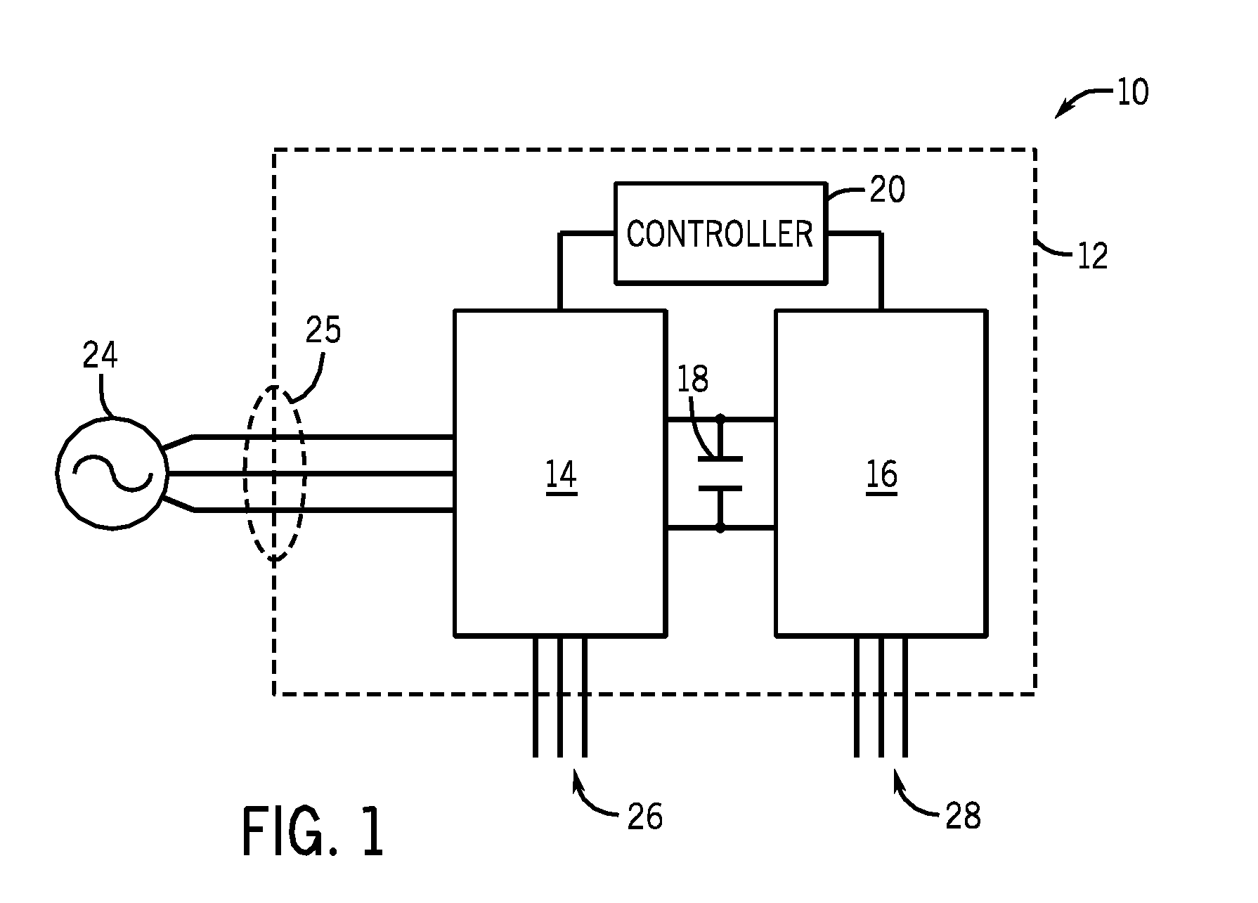
[0019]An example of a power conversion system in accordance with present embodiments is illustrated in the block diagram of FIG. 1. The system 10 includes a dual converter module 12, which includes 2 converter...


PUM


Abstract

The present invention includes techniques for configuring an electric drive module designed for various multi-axis drive system configurations. Embodiments include techniques for integrating a three phase dual converter with a diode bridge and drive controller within a single drive module. Further integrating the diode bridge directly within the drive module may result in an integrated, modular building block for multiple electric drive system configurations. In some embodiments, multiple electric drive modules are connected by a DC bus to form a system configured for higher energy efficiency.

Description

BACKGROUND[0001]The invention relates generally to the field of electric drives. More particularly, the invention relates to techniques for configuring electric drives in a multi-axis drive system.[0002]Various power systems include power conversion systems such as electric drives and motors which are employed to convert electrical energy into mechanical energy. An electric drive includes a device or group of devices which controls the torque, speed, position, and / or performance of an electric motor. The drive may be connected to a power source such as a battery, a power supply, or an AC generator. The electric drive controls the electric power from the power source to the motor, which converts the electrical power into mechanical power. The electric drive may also be connected to control circuitry configured to control the power conversion. For example, the control circuitry may control the current, voltage, and / or switching frequency of transistors in the drive.[0003]Electric driv...

Claims


Application Information

Patent Timeline
Patent Type & Authority Patents(United States)
IPC IPC(8): H02P23/00H02P21/00
CPCH02P27/06H02P21/0089
Inventor WINTERHALTER, CRAIG R.
Owner ROCKWELL AUTOMATION TECH
Learn More