

Ceramic electronic component
a technology of electronic components and ceramics, applied in the direction of fixed capacitor details, generators/motors, fixed capacitors, etc., can solve the problems of significant reduction of the bond strength between the metal terminal and eutectic solder fused, and the metal terminal is detached from the main body of the electronic component, so as to achieve low profile and difficult detachment
- Summary
- Abstract
- Description
- Claims
- Application Information
AI Technical Summary
Benefits of technology
Problems solved by technology
Method used
Image

Examples
Embodiment Construction
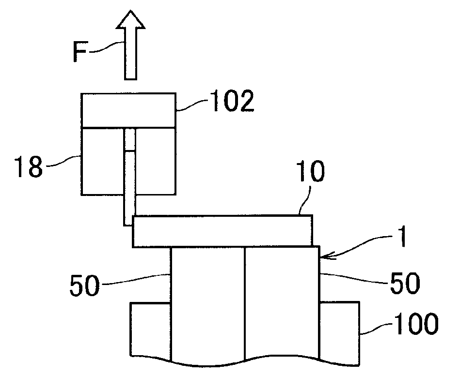
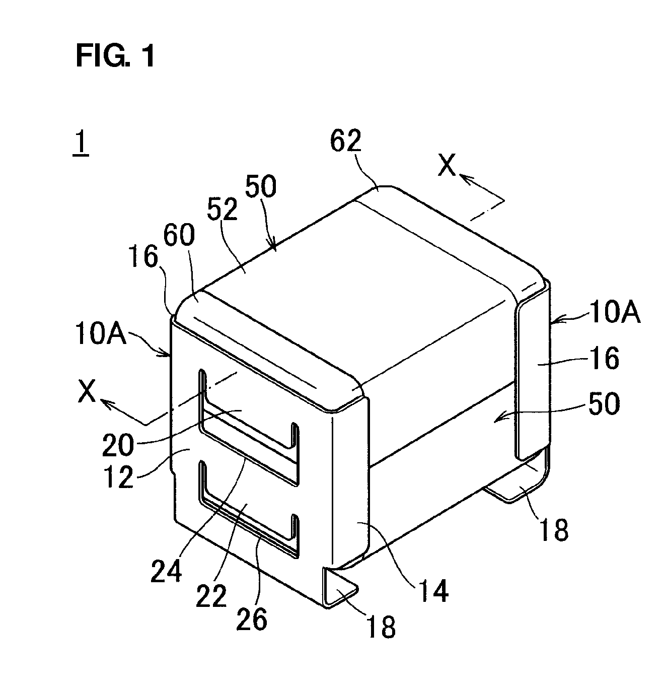
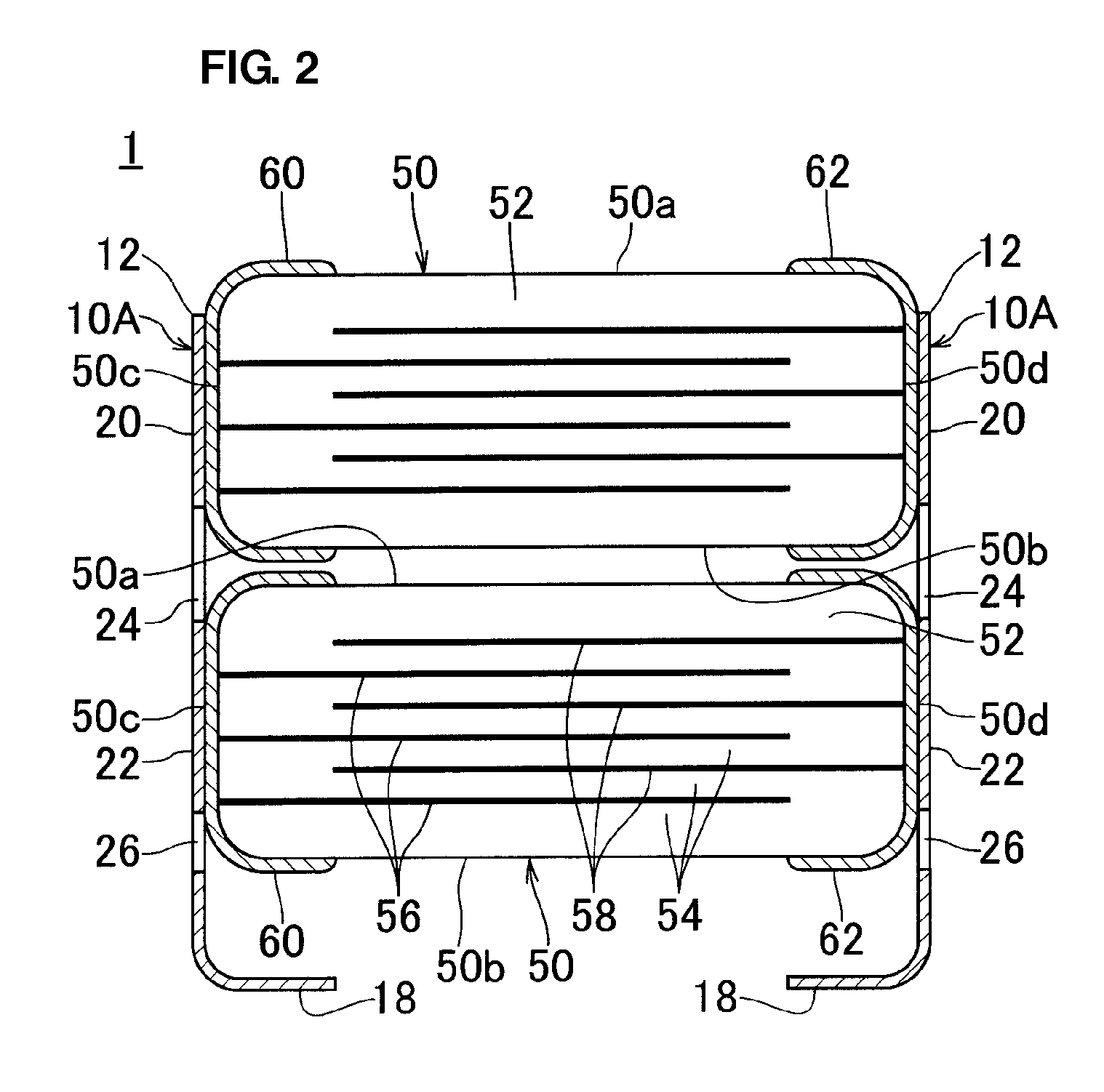
[0031]FIG. 1 is an external perspective view that illustrates a ceramic electronic component according to a preferred embodiment of the present invention. FIG. 2 is a cross-sectional view taken along X-X in FIG. 1. A ceramic electronic component 1 includes two metal terminals 10A used as one set and a stack of two electronic-component main bodies 50 sandwiched between the metal terminals 10A.
[0032]Each of the electronic-component main bodies 50 includes two opposed major surfaces 50a and 50b, two opposed end surfaces 50c and 50d, and two opposed side surfaces. The electronic-component main body 50 includes a stack 52 preferably having a substantially rectangular parallelepiped shape and external electrodes 60 and 62 disposed on both ends (end surfaces 50c and 50d), respectively. The stack 52 includes a plurality of ceramic layers 54 and internal electrodes 56 and 58 disposed between the ceramic layers 54. The corners and ridges of the stack 52 include rounded portions R.
[0033]The in...
PUM
 Abstract
Description
Claims
Application Information