
Flexible detonator integrated with directly written energetics

Inactive Publication Date: 2013-11-05
UNITED STATES OF AMERICA THE AS REPRESENTED BY THE SEC OF THE ARMY
View PDF4 Cites 8 Cited by
  • Summary
  • Abstract
  • Description
  • Claims
  • Application Information

AI Technical Summary

Benefits of technology

The patent text describes a new detonator design that uses a strong adhesion between a bridge wire and the detonator components. This adhesion makes the detonator resistant to high-G forces from acceleration and spin. The technical effect is a more reliable and secure detonator that can withstand high-velocity shells.

Problems solved by technology

A well known safety hazard of such electro-explosive devices is that they can be accidently fired by static electricity.
If the total resistance is too low, the one watt requirement will not be met; if it is too high, excessive heating due to higher power dissipation will result.
Typical processes for loading energetic materials (e.g. pressing, melt-pouring, or curing) are incompatible with the desire to reduce component size and mass.
Further, such applications often involving handling of dry energetic material, which presents safety concerns.

Method used


Image

  • Flexible detonator integrated with directly written energetics
  • Flexible detonator integrated with directly written energetics
  • Flexible detonator integrated with directly written energetics

Examples


Embodiment Construction

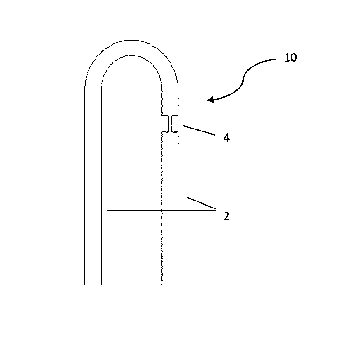
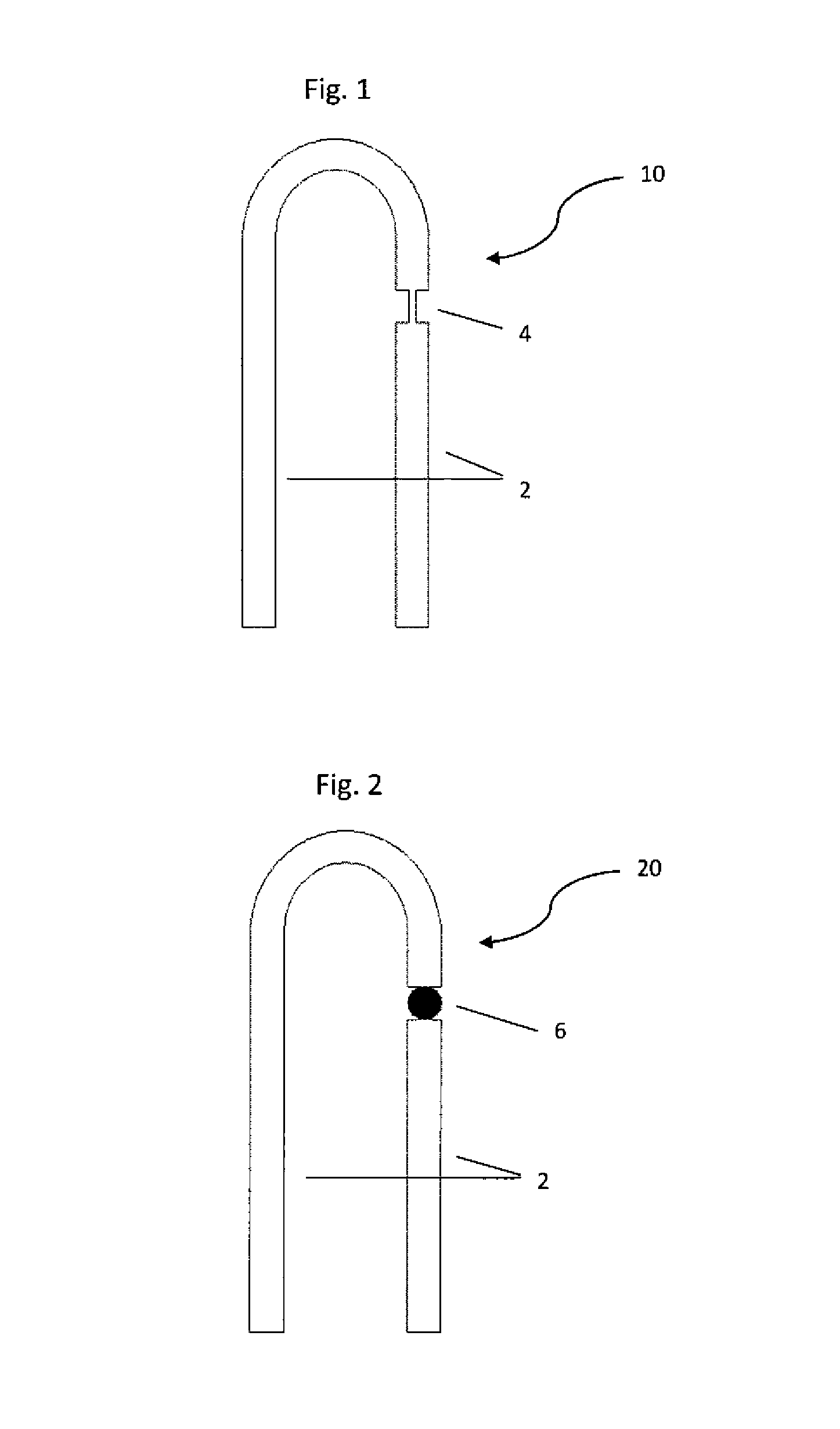
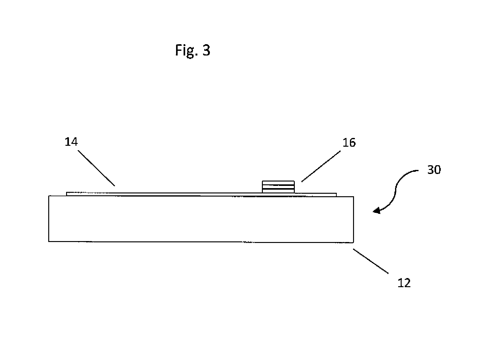
[0019]The present invention details a method of forming a bridge wire EED detonator on a flexible substrate, the process steps being: (1) printing a nano-particle conductive ink applied, using a piezo based drop on demand ink jet printer, to provide a finely detailed bridge wire EED set of conductive lead wires and a resistive bridge wire therebetween on a substrate, which substrate may be non-flexible, i.e. flat, or, flexible; (2) drying, i.e. annealing, the printed bridge wire EED to remove the solvent from the ink and leave a sintered, fully conductive, electrical circuit; (3) applying in layers, first a primary explosive layer (e.g. such as a lead styphnate based material); next, optionally, a transition explosive material layer (e.g. such as a lead azide based material); and finally, a secondary explosive material layer (e.g. such as a CL-20, RDX, HMX, PETN, TNAZ, and the like, based material) atop the bridge wire; and (4) allow each layer to dry, prior to applying the next wet...


PUM


Abstract

A method of forming a conductive ink bridge wire EED on either a flat or curved substrate, wherein a finely detailed bridge wire EED is printed on the substrate using a nano-particle conductive material applied with a commercially available piezoelectric drop-on-demand ink jet printer—which bridge wire is subsequently coated with a first primary explosive layer, an optional second transition explosive layer, and a third secondary explosive layer—such that upon creating a current through the bridge wire EED, the bridge wire is heated and the explosive layers detonate in turn, and in turn initiate the detonation of the device to which the detonator is attached.

Description

CROSS REFERENCE TO RELATED APPLICATIONS[0001]This application claims the benefit under 35 USC §119(e) of U.S. provisional patent application U.S. 61 / 345,697, filed on May 18, 2010, which provisional application is co-pending herewith, and is hereby incorporated herein by reference.FEDERAL RESEARCH STATEMENT[0002]The inventions described herein may be manufactured, used, and licensed by, or for the U.S. Government, for U.S. Government purposes.BACKGROUND OF INVENTION[0003]1. Field of the Invention[0004]The present invention relates to electro-thermal initiated explosive devices, and in particular, to a method of forming a bridge wire resistance element, integral with a composite primary and secondary set of charges, that can be directly applied to a flexible substrate.[0005]2. Related Art[0006]Electro-explosive devices (EED's) are well known in the art and include such devices as primers, detonators, and squibs. These devices generally include a pair of lead wires which are connected...

Claims


Application Information

Patent Timeline
IPC IPC(8): F42B3/12F42B3/195
CPCF42B3/12F42B3/195
Inventor FUCHS, BRIAN E.ZUNINO, III, JAMES L.SCHMIDT, DANIEL P.STEC, III, DANIELPETROCK, ANNE MARIE
Owner UNITED STATES OF AMERICA THE AS REPRESENTED BY THE SEC OF THE ARMY
Learn More