Light device with enhanced flow rate and cooling efficiency and reduced noise and a cooling unit thereof

a technology of flow rate and cooling efficiency, which is applied in the direction of semiconductor devices for light sources, discharge tube main electrodes, lighting and heating apparatus, etc., can solve the problems of low flow rate, low cooling efficiency and flow rate, large operation noise, etc., and achieve enhanced flow rate and cooling effect, smooth guide air current, and low manufacturing cost

Inactive Publication Date: 2013-11-05
SUNONWEALTH ELECTRIC MACHINE IND
View PDF3 Cites 2 Cited by
  • Summary
  • Abstract
  • Description
  • Claims
  • Application Information

AI Technical Summary

Benefits of technology

[0008]It is therefore the primary objective of this invention to provide a light device and a cooling unit thereof, with a driving member directly mounted on a heat dissipating seat of the cooling unit to smoothly guide the air current in an inner air channel of the heat dissipating seat, so as to enhance flow rate and cooling effect and lower operation noise.
[0009]Another objective of this invention is providing a light device and a cooling unit thereof merely forming the inner air channel inside the heat dissipating seat while an outer air channel is formed between the heat dissipating seat and a housing, so as to simplify the structure and manufacture cost thereof.

Problems solved by technology

However, since the cooling fan 93 of the light device 9 includes the casing 931, the bottom of the casing 931 extending between the receiving room 921 and the second air channel 923 can easily lead to turbulence causing large operation noise, low cooling efficiency and a low flow rate.
Besides, the structure of the heat sink 92 is complex for forming the first and second air channel 922, 923, and thus the heat sink 92 of the light device 9 will lead to high manufacture cost.

Method used


Image

  • Light device with enhanced flow rate and cooling efficiency and reduced noise and a cooling unit thereof
  • Light device with enhanced flow rate and cooling efficiency and reduced noise and a cooling unit thereof
  • Light device with enhanced flow rate and cooling efficiency and reduced noise and a cooling unit thereof

Examples


Embodiment Construction

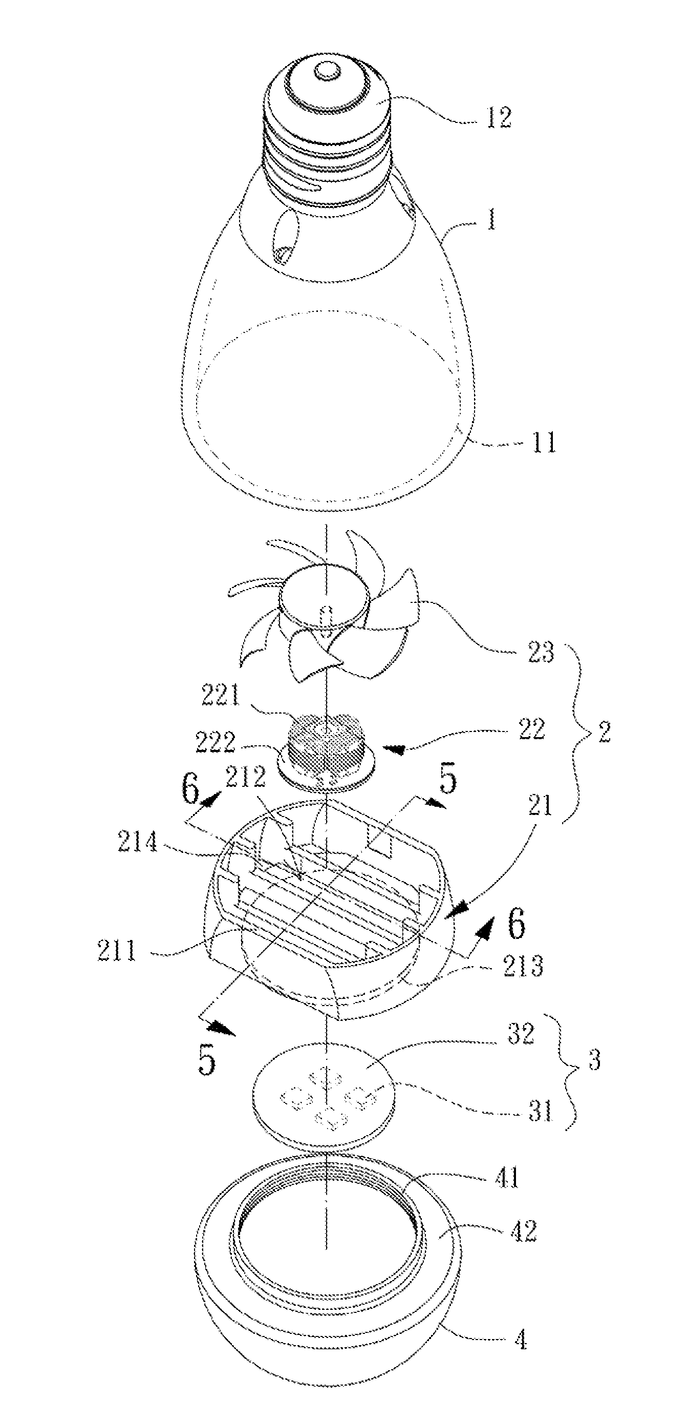
[0029]Please refer to FIGS. 4-7. A light device according to a first embodiment of the invention is shown, which includes a housing 1, a cooling unit 2 received in the housing 1, and a light emitting unit 3 coupled with the cooling unit 2.

[0030]The housing 1 is a hollow case with an assembly opening 11 and an electrical base 12 arranged at two ends of the housing 1, which are preferably two opposite ends of the housing 1 as shown in FIG. 4. The assembly opening 11 communicates with an inner room of the housing 1 for the cooling unit 2 to be inserted into the inner room via the assembly opening 11. The electrical base 12 is adapted to connect with a lamp holder for accessing electrical power.

[0031]The cooling unit 2 received in the inner room of the housing 1 has a heat dissipating seat 21, a driving member 22 and a fan wheel 23. The heat dissipating seat 21 is made of heat conductive material such as aluminum ally and has a lateral wall 211, an inner air channel 212, a base portion ...


PUM


Abstract

A light device including a housing, a cooling unit and a light emitting unit is disclosed. The housing has an assembly opening and an electrical base. The cooling unit is in the housing and has a heat dissipating seat, a driving member electrically connecting with the electrical base, and a fan wheel rotatably coupled with the driving member. The heat dissipating seat has a lateral wall coupled with the housing, an inner air channel formed in the lateral wall, a base portion arranged in the inner air channel for the driving member to be mounted, and at least one through hole penetrating the base portion and communicating with the inner air channel. The light emitting unit is coupled with the heat dissipating seat and electrically connects with the electrical base. An outer air channel is formed between the lateral wall and the housing.

Description

BACKGROUND OF THE INVENTION[0001]1. Field of the Invention[0002]The present invention relates to a light device and, more particularly, to a light device with high cooing efficiency and low operation noise.[0003]2. Description of the Related Art[0004]Referring to FIGS. 1-3, a conventional light device with a cooling unit is disclosed, wherein the conventional light device labeled as “9” includes a housing 91, a heat sink 92, a cooling fan 93, a light emitting unit 94 and a light-permeable bulb 95. The housing 91 has an assembly opening 911. The heat sink 92 is mounted in the housing 91 via the assembly opening 911 and has a receiving room 921 on one side, a first air channel 922 communicating the outside and the inside of the housing 91, and a second air channel 923 communicating the bottom of the receiving room 921 and the outside of the housing 91. The cooling fan 93 includes a casing 931 forming a cylindrical channel and received in the receiving room 921, a driving motor (not il...

Claims


Application Information

Patent Timeline
Patent Type & Authority Patents(United States)
IPC IPC(8): F21V29/00F21V29/02H01J61/52H01L33/64
CPCF21K9/135F21V29/02F21K9/232F21V29/83F21V29/67
Inventor FANG, I-LE
Owner SUNONWEALTH ELECTRIC MACHINE IND
Why Eureka
Try Eureka