Round cutting insert with anti-rotation feature

a cutting insert and anti-rotation technology, which is applied in the field of cutting inserts, can solve the problems of affecting the quality of the cut on the workpiece, and affecting the quality of the cu

Active Publication Date: 2013-11-05
KENNAMETAL INC
View PDF167 Cites 29 Cited by
  • Summary
  • Abstract
  • Description
  • Claims
  • Application Information

AI Technical Summary

Benefits of technology

[0004]The present invention provides a round cutting insert with an anti-rotation feature. The round cutting insert includes a plurality of projections formed on a first surface and another plurality of projections formed on an opposing surface. The round cutting insert is reversible and indexable. The round cutting insert is removably received in an insert receiving pocket in a tool body wherein the insert receiving pocket includes a plurality of dimples for receiving one of the plurality of first projections or the plurality of second projections. This arrangement prevents rotation of the round cutting insert while mounted in the insert receiving pocket.
[0007]A further aspect of the present invention is to provide an anti-rotation mounting arrangement between a round cutting insert and an insert receiving pocket in a tool body. The round insert includes a first portion that terminates in a first cutting edge, a second portion that terminates in a second cutting edge, and a circular side surface between the first portion and the second portion. The anti-rotation mounting arrangement includes a plurality of first projections extending from the first portion, a plurality of second projections extending from the second portion, and a plurality of dimples formed in the insert receiving pocket for cooperating with and receiving one of the plurality of first projections or the plurality of second projections to prevent rotation of the round cutting insert while mounted in the insert receiving pocket.
[0008]Another aspect of the present invention is to provide a cutting tool assembly having a tool body, an insert, and a fastening screw. The tool body includes an insert receiving pocket. The insert is received in the insert receiving pocket and the insert has a first portion having a first cutting edge generally disposed about an outer periphery of the first portion and a second portion having a second cutting edge generally disposed about an outer periphery of the second portion. The insert defines a non-cylindrical opening extending axially through the insert from the first portion to the second portion. The fastening screw extends through the non-cylindrical opening to removably secure the insert to the insert receiving pocket of the tool body.

Problems solved by technology

During a cutting operation, such inserts often experience not only compressive and vibratory forces, but some amount of torque due to the angle between the cutting edges of the inserts and the workpiece.
If the clamping screw should become sufficiently loosened, it can vibrate within the surrounding pocket severely enough to become chipped or cracked not only ruining the insert, but also jeopardizing the quality of the cut on the workpiece.

Method used


Image

  • Round cutting insert with anti-rotation feature
  • Round cutting insert with anti-rotation feature
  • Round cutting insert with anti-rotation feature

Examples


Embodiment Construction

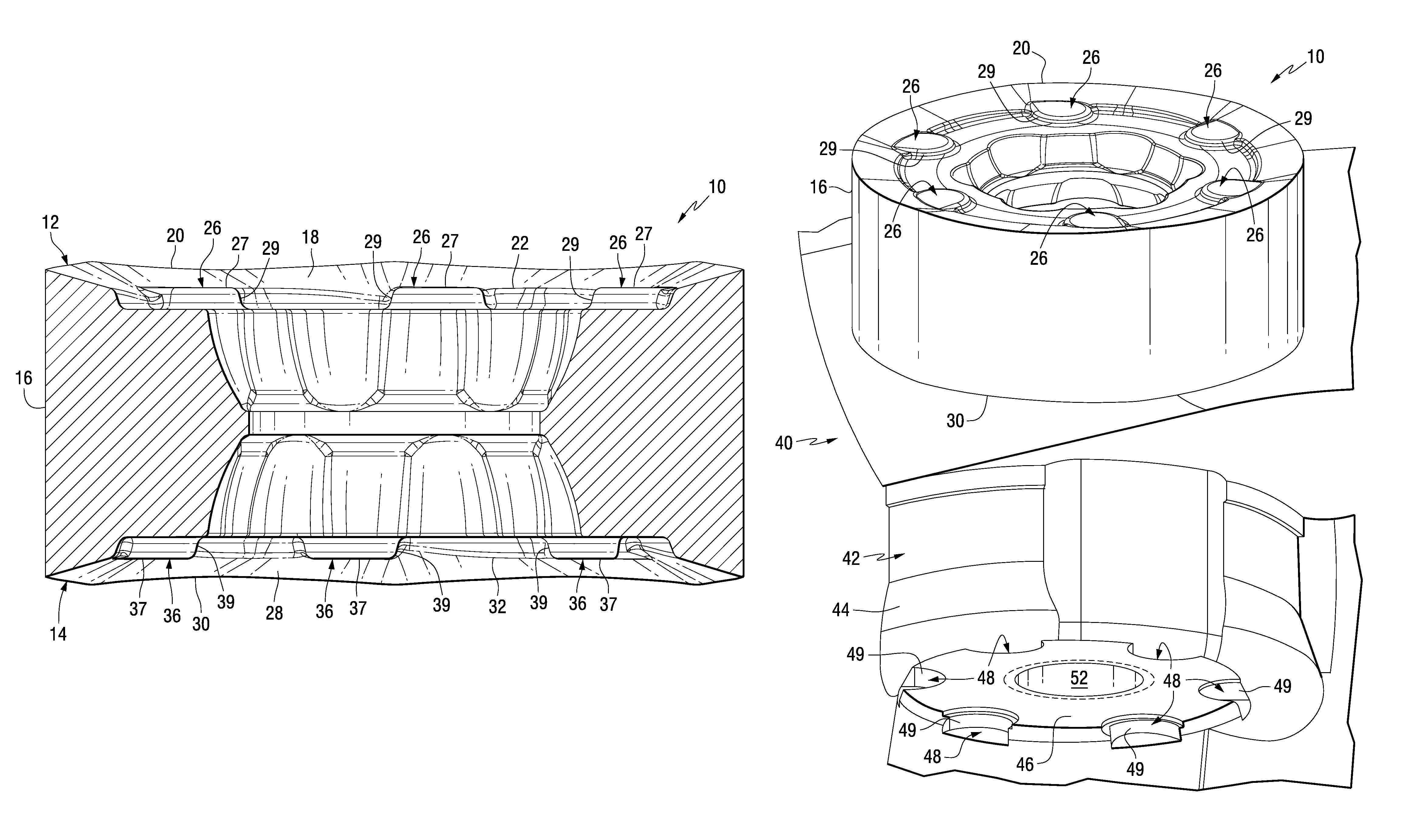
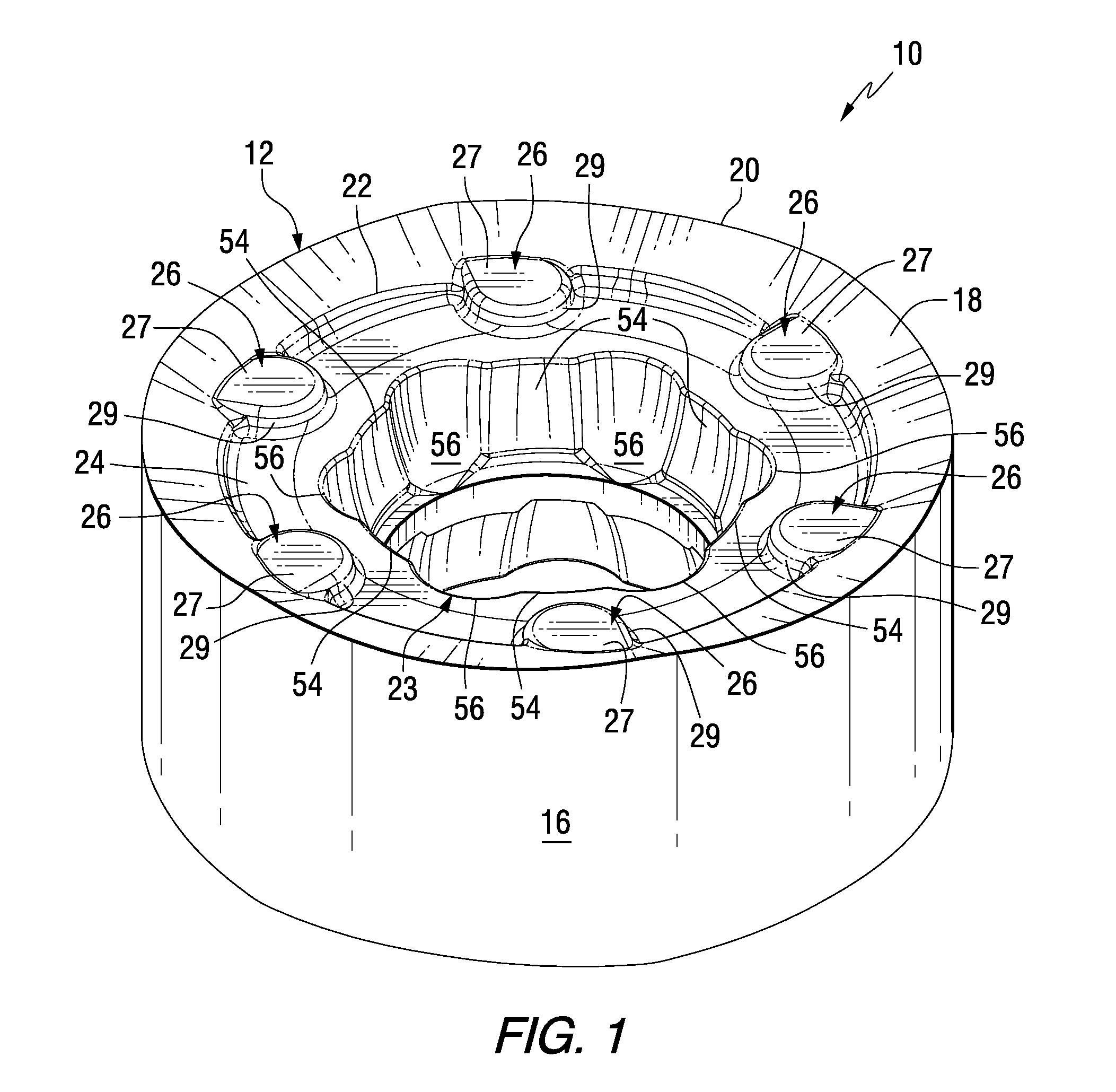
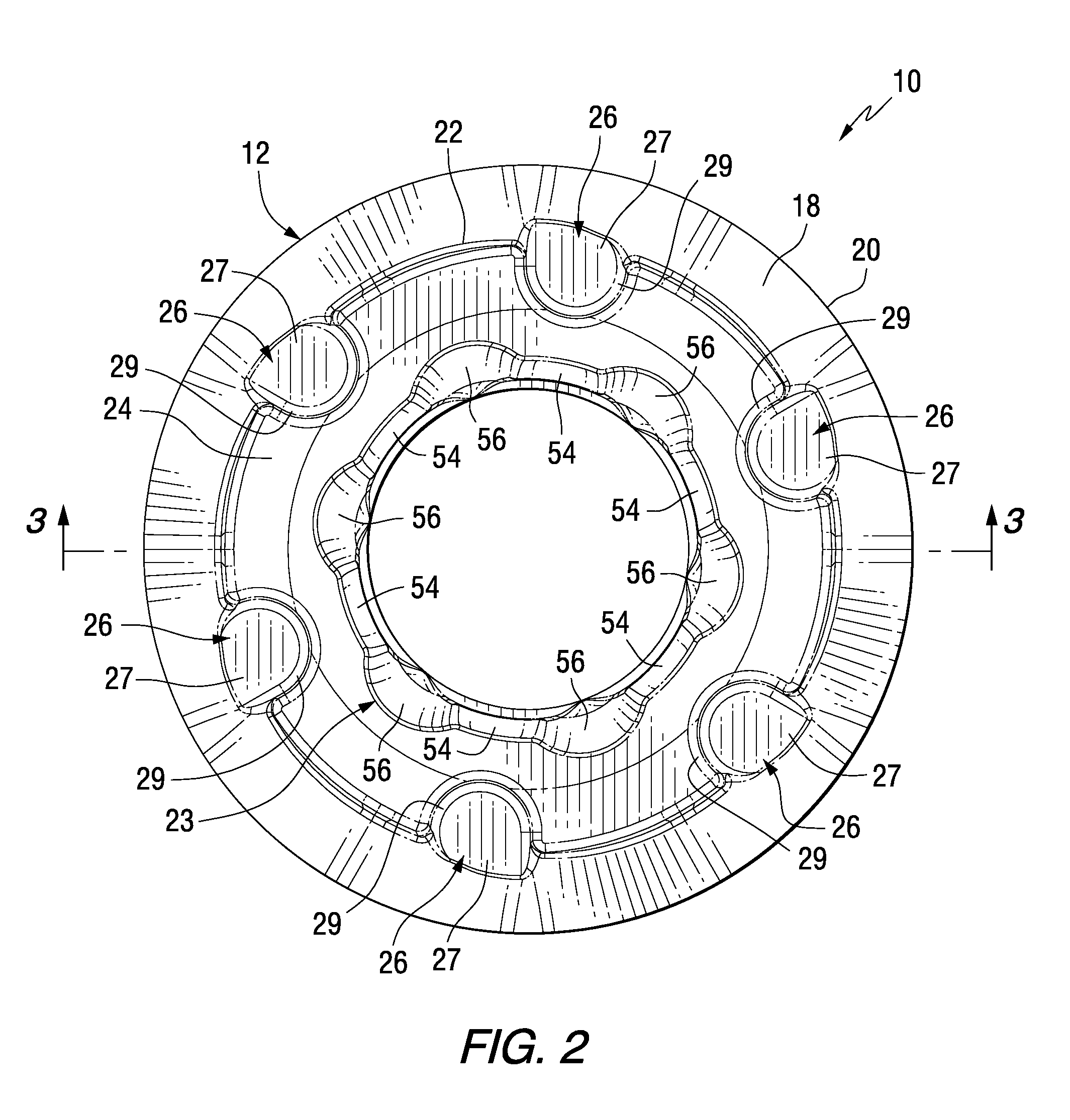
[0018]Referring to the Figures, there is illustrated a cutting insert 10, in accordance with an aspect of the invention. The cutting insert 10 includes a first or top portion 12 (see generally FIGS. 1, 2, 3 and 5) and a second or bottom portion 14 (see generally FIGS. 3, 4 and 5) and a generally circular side portion 16 that extends between the first portion 12 and the second portion 14. Thus, it will be appreciated that the cutting insert 10 is a generally round cutting insert for positioning in a tool body for performing a cutting operation on a workpiece (not shown) as will be described in more detail herein.

[0019]As shown in FIGS. 1 and 2, the cutting insert 10 includes a first outer surface 18 that terminates in a generally outwardly direction in a first cutting edge 20 and terminates in a generally inwardly direction in a first inner edge 22. In one aspect, the first outer surface 18 slopes from the first cutting edge 20 toward the first inner edge 22. The cutting insert 10 al...


PUM

PropertyMeasurementUnit
compressiveaaaaaaaaaa
vibratory forcesaaaaaaaaaa
torqueaaaaaaaaaa

Abstract

A round cutting insert with an anti-rotation feature. The round cutting insert includes a plurality of projections formed on a first surface and another plurality of projections formed on an opposing surface. The round cutting insert is reversible and indexable. The round cutting insert is removably received in an insert receiving pocket in a tool body wherein the insert receiving pocket includes a plurality of dimples for receiving one of the plurality of first projections or the plurality of second projections. This arrangement prevents rotation of the round cutting insert while mounted in the insert receiving pocket.

Description

BACKGROUND OF THE INVENTION[0001]The invention relates generally to cutting inserts and, more particularly, relates to round cutting inserts having an anti-rotation feature for preventing rotation of the round cutting insert mounted onto the body of a cutting tool.[0002]The inserts used in tools such as, for example, milling cutters are mounted in complementarily-shaped pockets spaced around the periphery of the tool body. The inserts are typically secured within their respective pockets by clamping screws inserted through a hole provided in the center of the insert. During a cutting operation, such inserts often experience not only compressive and vibratory forces, but some amount of torque due to the angle between the cutting edges of the inserts and the workpiece. For cutting inserts of non-round shapes, such torque does not result in the rotation of the insert due to the interference-type fit between the angled sidewalls of such inserts and the complementarily-shaped walls of th...

Claims


Application Information

Patent Timeline
Patent Type & Authority Patents(United States)
IPC IPC(8): B23C5/08B23C5/02
CPCB23C5/2213B23C2200/045B23C2200/081B23C2200/161B23C2200/168B23C2210/168Y10T407/1934Y10T407/20Y10T407/23Y10T407/1924Y10T407/24Y10T407/1936Y10T407/235Y10T407/2268B23B27/16B23C5/20B23C5/22
Inventor MORRISON, LEWIS RAYMYLAVARAM NIKHILESH, KUMAR REDDYLONG, THOMAS JERRYKOVAC, JEFFREY FRANCISMALI, SURESH
Owner KENNAMETAL INC
Why Eureka
Try Eureka