
Bone screws and methods of use thereof

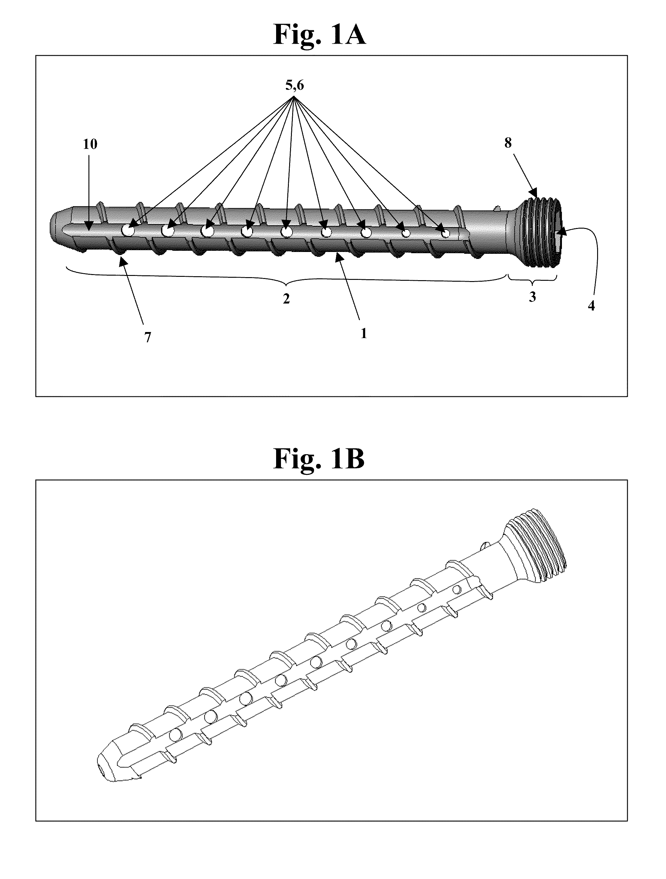
a bone screw and screw technology, applied in the field of bone screws, can solve the problems of screw loosening, screw loosening, and bone screw backout, and achieve the effect of faster advance of bone screw and flow more easily through the delivery channel

Active Publication Date: 2013-11-05
INNOVISION CO LTD
View PDF149 Cites 66 Cited by
  • Summary
  • Abstract
  • Description
  • Claims
  • Application Information

AI Technical Summary

Benefits of technology

[0014]In yet another embodiment, the bone screw further includes an internal plug that fully or partially occludes the interior channel within the screw body and that is stationary within, or slidably movable along, the interior channel. In other embodiments, the plug is positioned at the hollow tip of a fully cannulated screw to prevent escape of flowable medium from the tip, or it is positioned on, in, or close to the screw head in order to prevent escape of flowable medium from the screw head or entry of other substances into the screw head and interior channel. The plug can be placed entirely inside the interior channel, or it can screw into place within the screw head and extend a designated distance into the interior channel. The plug can be designed to occlude all, or any subset of, delivery channels (e.g., 1, 2, 5, 10, 20, 30, 50, or more delivery channels).
[0024]In another embodiment of all aspects of the invention, the bone screw includes a dual lead (e.g., two threads 180 degrees apart winding around the axis of the screw body), which provides for a faster advance of the screw in the bone. Alternatively, the bone screw can be designed as a dual lead, but have one thread omitted, which provides extra space between the thread for delivery channels.
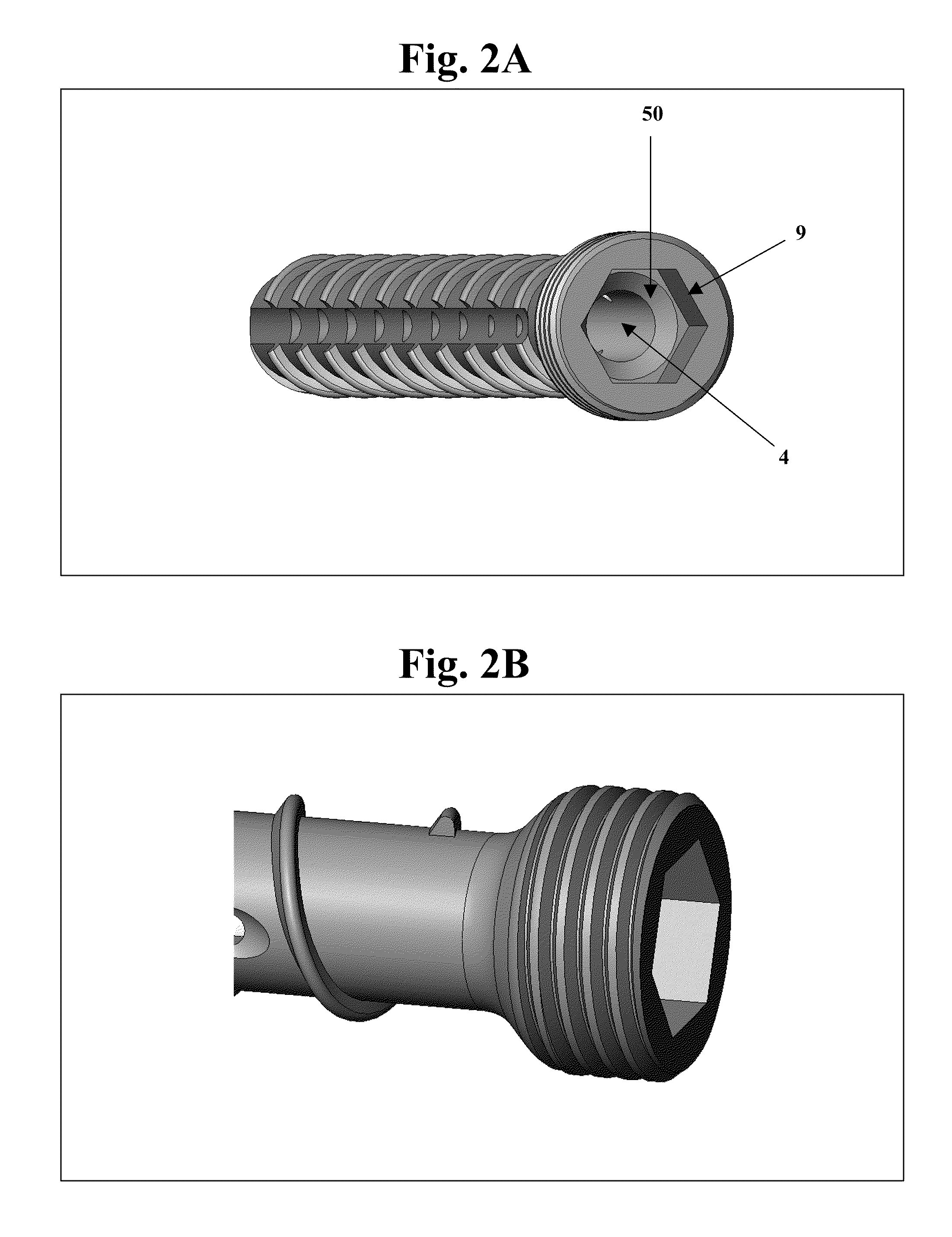
[0025]In still another embodiment of all aspects of the invention, the bone screw includes a screw head, the circumference of which includes an internal edge break or chamfer on the inside of the radial hole just beyond the exterior of the screw head. The internal edge break or chamfer allows the flowable medium injected into the interior delivery channel (or cannula) of the bone screw to flow more easily through the delivery channel.
[0033]By “flowable medium” is meant, generally, a formulation of a resorbable or non-resorbable biocompatible agent, e.g., a polymer, such as a thermoset polymer or a thermoplastic polymer, e.g., PMMA (polymethylmethacrylate), a bone void filler material, a cement, or a pharmaceutical agent. In particular, the flowable medium may be a resorbable calcium phosphate or calcium sulphate cement, which may allow for the gradual replacement of the agent with bone. Both resorbable and non-resorbable biocompatible agents, such as bone cements, have been used successfully in the treatment of bone defects.

Problems solved by technology

One drawback associated with prior art bone screws is the potential for the bone screw to back out after implantation.
The use of a solid screw with a bone cement or other fillable material may increase the initial stiffness and strength of the repair, but may not significantly decrease loosening of the screw at the repair site.
The substitution of solid screws with cannulated screws that can extrude a bone cement or other fillable material may improve the strength of the repair while at the same time reducing the likelihood that the screw will loosen and pull out, but distribution of the bone cement or fillable material through the screw and throughout the repair site remains a problem.

Method used


Image

  • Bone screws and methods of use thereof
  • Bone screws and methods of use thereof
  • Bone screws and methods of use thereof

Examples


example 1

Use of a Bone Screw of the Invention to Repair a Fracture or Other Bone Defect

[0113]A bone screw of the invention can be used to provide fracture support, e.g., for a subarticular fracture, in conjunction with conventional fixation. The site to be supported can be accessed using either a percutaneous or open technique. The extraction technique preferably ensures maximal bone conservation.

[0114]Uni-Cortical and Bi-Cortical Fixation

[0115]A bone screw of the invention can be used for uni-cortical fixation to cross one of the sections of the thick cortical wall of a bone, as shown schematically in FIG. 18A. An exemplary bone screw for uni-cortical fixation is, e.g., 25-55 mm long, with, e.g., a 4.0 mm major diameter and, e.g., a 1.6 mm interior channel diameter.

[0116]Alternatively, for bi-cortical fixation, the bone screw penetrates all the way through the bone and reaches the opposite thick cortical wall, as shown schematically in FIG. 18B. An exemplary bone screw for bi-cortical fixat...

example 2

Use of a Bone Screw of the Invention to Facilitate Dental Implant

[0122]A blind hole created during tooth replacement often requires a bone graft in order to provide support for the post of a dental implant. A bone screw of the invention can be used to facilitate placement of such an implant. As shown in FIGS. 20A-20D, a bone screw optimized for dental applications contains a curved cap affixed to the screw head. For example, the bone screw can have an interior channel diameter of 1.0-2.0 mm, e.g., 1.2 mm, and a major diameter of 3.0-5.0 mm, e.g., 3.0 mm.

[0123]The bone screw is first inserted into, e.g., the maxilla or mandible, and bone cement or other flowable medium is injected and evenly distributed along the axis of the hole. The curved cap is shaped to contain the flowable medium. The cement can act to rebuild the lost bone stock, which allows for increased height of bone anchorage and permits sufficient stability for subsequent insertion of a dental implant over the bone screw...

example 3

Use of a Bone Screw of the Invention to Repair Fractures Near Joints that are Reconstructed but do not Have Enough Load-Bearing Strength with Conventional Fixation Alone

[0125]A patient presents with a fracture of the tibia or femur occurring near the tibial-femoral or tibial-talar joint. For example, in a high-speed automobile collision, the femur just above the knee can break when the crash victim's bent leg hits the dashboard. The bone may break into two, three, or more pieces. The site to be repaired can be accessed using a percutaneous or open technique. The small profile of cement connection means the screw and cement can be done with a wide incision (open) or with a very small incision (closed).

[0126]By using a bone screw of the invention, subsequent screw removal is possible while ensuring maximal bone conservation. For example, a screw designed for use with an interior rotational driver, e.g., an internal hex driver, eliminates the need to use a large external driver, e.g., ...


PUM


Abstract

The invention features bone screws having a threaded screw body and a screw head attached to one end of the screw body, the bone screw further including: a) an interior channel extending longitudinally through the screw head and through at least a portion of the screw body, wherein the interior channel has a width of less than 5.0 millimeters; and b) a plurality of radially-disposed delivery channels connecting the interior channel to the exterior of the screw body, each delivery channel having exterior openings. The invention further features devices that include a bone screw and a delivery manifold detachably attached to the screw head of the bone screw. In addition, the invention features methods of treating a patient having a bone defect by using a bone screw described herein.

Description

FIELD OF THE INVENTION[0001]The invention relates to devices, in particular, bone screws, and methods of use thereof for the treatment of bone defects.BACKGROUND OF THE INVENTION[0002]Fixation tools and devices, which are available in a wide variety of different shapes and sizes, have long been used in the repair of bone defects, such as bone fractures. A physician typically sets the bone to be repaired in the proper position and then uses the fixation tools and devices to secure the bone in that position during the healing process.[0003]A fixation device, such as a bone plate or rod, can be secured to the bone by a fixation tool, such as a bone screw. Alternatively, a bone screw can be used by itself to repair a bone defect. One drawback associated with prior art bone screws is the potential for the bone screw to back out after implantation. To inhibit back out, bone screws have been modified with various thread designs and locking features, with some success.[0004]When installing ...

Claims


Application Information

Patent Timeline
Patent Type & Authority Patents(United States)
IPC IPC(8): A61F2/08A61B17/04A61B17/86
CPCA61B17/0401A61B17/7098A61B17/8057A61B17/864A61C8/0022A61B17/8811A61B17/8605A61B17/861A61B17/8875A61B2017/044A61C8/0006A61B17/80A61B2017/561
Inventor RUSSELL, THOMAS A.GLOVER, TODD A.HOUSTON, SAMUEL A.PEPPER, JOHN R.
Owner INNOVISION CO LTD
Learn More