Concentration sensor device and concentration detecting method
a sensor device and concentration technology, applied in chemical methods analysis, generators/motors, instruments, etc., can solve the problems of water being mixed in the mixture fuel by human error, water being contaminated with water, and generating measurement errors
- Summary
- Abstract
- Description
- Claims
- Application Information
AI Technical Summary
Benefits of technology
Problems solved by technology
Method used
Image
Examples
first embodiment
(First Embodiment)
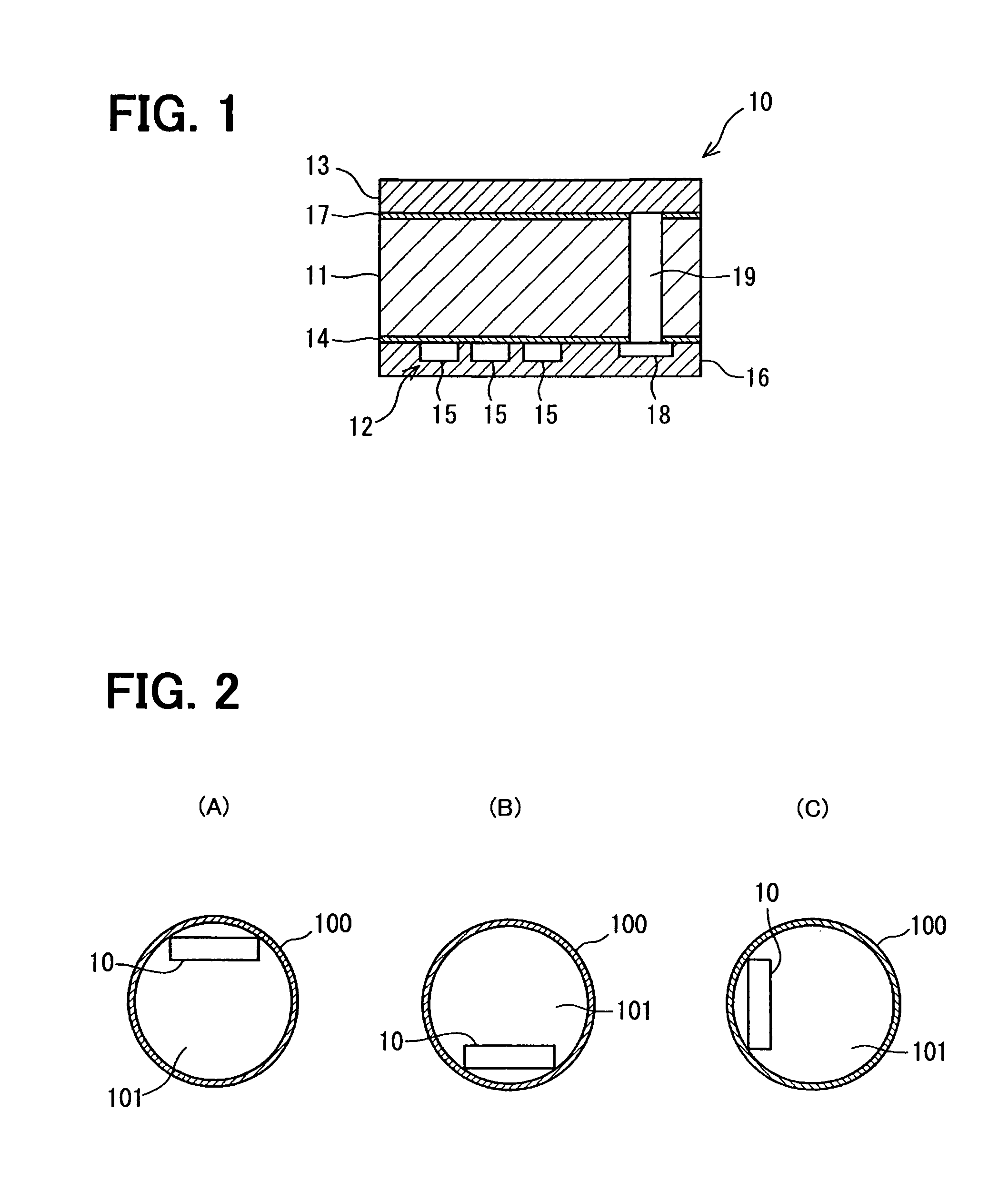
[0143]FIG. 1 shows a concentration sensor device according to a first embodiment. As shown in FIG. 1, a concentration sensor device 10 of the first embodiment includes a substrate 11, a sensor unit 12 and a piezoelectric element 13. The substrate 11 is made of a silicon semiconductor, for example. As shown in FIG. 2, the concentration sensor device 10 is arranged in a pipe portion 100 through which mixture fuel flows. The concentration sensor device 10 is arranged to an upper part shown in FIG. 2(A), a bottom part shown in FIG. 2(B), or a side part shown in FIG. 2(C) of the pipe portion 100.
[0144]As shown in FIG. 1, the sensor unit 12 is arranged on a first face of the substrate 11. An insulation film 14 is arranged between the sensor unit 12 and the substrate 11. The insulation film 14 is a silicon oxide film, for example. The sensor unit 12 has plural electrodes 15. For example, a permittivity and a relative permittivity between the electrodes 15 of the sensor un...
second and third embodiments
(Second and Third Embodiments)
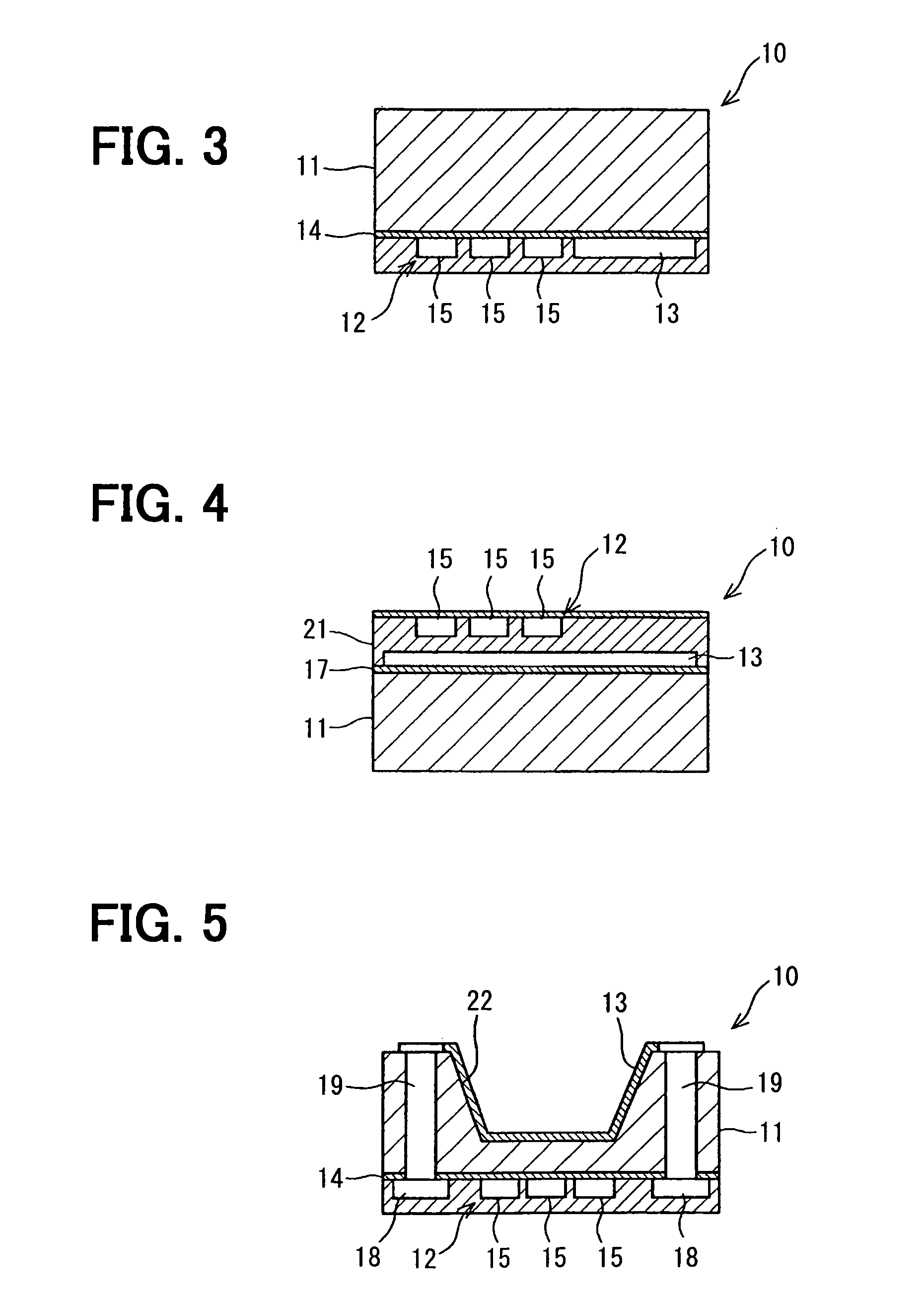
[0151]A concentration sensor device according to a second embodiment is shown in FIG. 3, and a concentration sensor device according to a third embodiment is shown in FIG. 4.
[0152]In the second embodiment, as shown in FIG. 3, the sensor unit 12 and the piezoelectric element 13 are arranged on the same face of the substrate 11. In a case that the sensor unit 12 and the piezoelectric element 13 are arranged on the same face of the substrate 11, a size of the device 10 may be increased to secure a location area for the sensor unit 12 and the piezoelectric element 13. If the size of the device is maintained without the increasing, a vibration area of the piezoelectric element 13 may be decreased. In contrast, when the sensor unit 12 and the piezoelectric element 13 are arranged on the same face of the substrate 11, the sensor unit 12 and the piezoelectric element 13 are arranged adjacent to each other. Thus, because the sensor unit 12 directly vibrates due ...
fourth embodiment
(Fourth Embodiment)
[0155]FIG. 5 shows a concentration sensor device according to a fourth embodiment.
[0156]As shown in FIG. 5, a concentration sensor device 10 according to the fourth embodiment has a recess 22 defined in the substrate 11. The recess 22 has a diaphragm shape recessed from a first face of the substrate 11 toward a second face of the substrate 11 opposite from the first face. The sensor unit 12 and the circuit unit 18 are arranged on a flat face of the substrate 11 opposite from the recess 22. The piezoelectric element 13 is arranged along an open end face of the recess 22, thereby the piezoelectric element 13 covers an open face of the recess 22 of the substrate 11. Thus, the piezoelectric element 13 is arranged opposite from the sensor unit 12 and the circuit unit 18 through the substrate 11.
[0157]The device 10 includes the through electrode 19 passing through the substrate 11 in the thickness direction. A first end of the through electrode 19 is connected to the ci...
PUM
| Property | Measurement | Unit |
|---|---|---|
| relative permittivity | aaaaa | aaaaa |
| relative permittivity | aaaaa | aaaaa |
| relative permittivity | aaaaa | aaaaa |
Abstract
Description
Claims
Application Information
 - R&D
- Intellectual Property
- Life Sciences
- Materials
- Tech Scout
- Unparalleled Data Quality
- Higher Quality Content
- 60% Fewer Hallucinations
Browse by: Latest US Patents, China's latest patents, Technical Efficacy Thesaurus, Application Domain, Technology Topic, Popular Technical Reports.
© 2025 PatSnap. All rights reserved.Legal|Privacy policy|Modern Slavery Act Transparency Statement|Sitemap|About US| Contact US: help@patsnap.com


