
Arrow shaft having front/rear two-stage spine structure

a spine structure and arrow shaft technology, applied in the field of arrow shafts, can solve the problems of machining defects that can be easily encountered, the effect of such an archer's paradox on the arrow shaft can be more severe than thought, and the flight stability and straight advancing property of the arrow can be improved

Active Publication Date: 2013-11-12
SONG JIN HEE
View PDF10 Cites 14 Cited by
  • Summary
  • Abstract
  • Description
  • Claims
  • Application Information

AI Technical Summary

Benefits of technology

The present invention provides an improved arrow shaft design that addresses common issues in the related art. The arrow shaft is divided into two parts along its length, with each part laminated and wound with a different carbon fabric sheet to achieve improved durability, prevented splitting, and optimized flight performance. Additionally, the front and rear parts of the shaft have different strengths, allowing for differential material properties without additional cost. Compared to existing designs, the present invention has superior strength, is less prone to splitting, and has a simpler manufacturing process for increased productivity.

Problems solved by technology

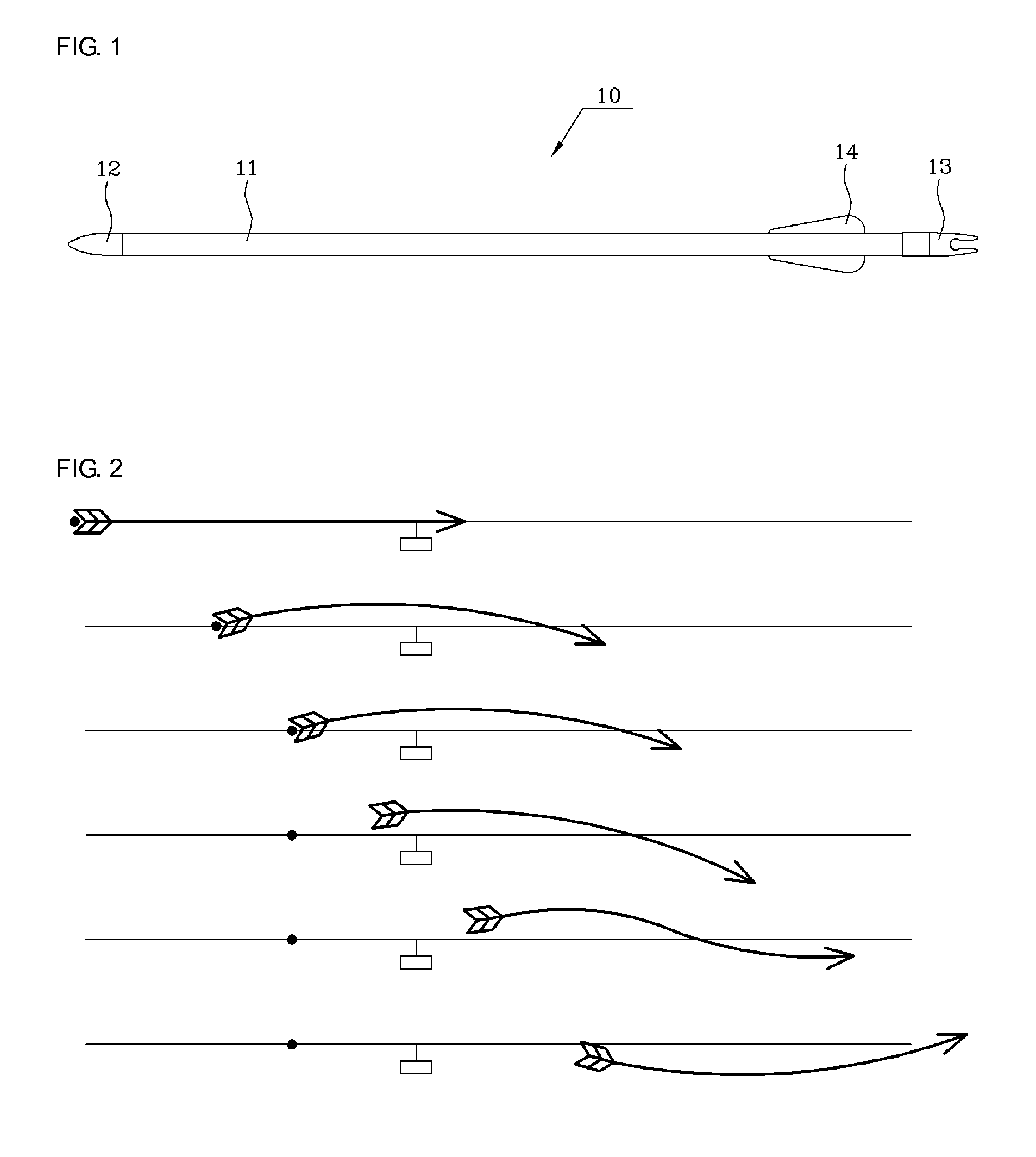
In shooting the arrow, because kinetic energy is momentarily transferred to the arrow as if the arrow were in a stopped state, while the string is released, the arrow cannot withstand such a force.
Therefore, the effects of such an archer's paradox on the arrow shaft can be more severe than thought.
However, because the diameter of the arrow shaft of such a product is adjusted by grinding the carbon fiber sheet layer, there are the problems of maintaining the dimensions thereof, a machining defect can be readily occurred in an inside texture of the sheet layer upon grinding, and an eccentric nature can be imposed on the arrow shaft due to failure of managing the dimensions precisely.
In addition, bonding between the aluminum core and the carbon fiber sheet layer which are different materials can be difficult, and the weight of the arrow shaft can be increased because the aluminum tube is included therein.
This is a critical problem.
Also, because outer peripheral surfaces of the front and rear portions of the arrow shaft must be grounded to impart it with the required diameter, the waste of material can be serious and the processing time it takes to do the machining can be extended, leading to a decrease in productivity.
In this case, if the strength, weight and length of the arrow shaft are not suitable for the strength of the bow, the arrow cannot fly in a straight line.
However, because the spine of the arrow has to be determined in consideration of the strength of the bow, it is not always advantageous for the spine to be unconditionally increased.
In addition, when increasing the spine of the arrow, material and manufacturing costs can be increased.
Specifically, the middle portion of the arrow shaft is subjected to frequently repeated bending forces due to the archer's paradox phenomenon as described above, and is likely to be weakened thereby after being used for a long term, and the front portion of the arrow shaft to which an arrow head is coupled is subject to most of the impact of hitting a target when frequently shooting.
Therefore, although materials having different physical properties were required to be used depending on each of the locations in fabricating the arrow shaft, conventional arrows have been fabricated of only a single sheet material and such needs have not satisfied.
Therefore, there are problems that the operation is complex and the number of steps is increased, leading to decreasing the productivity.

Method used


Image

  • Arrow shaft having front/rear two-stage spine structure
  • Arrow shaft having front/rear two-stage spine structure
  • Arrow shaft having front/rear two-stage spine structure

Examples


Embodiment Construction

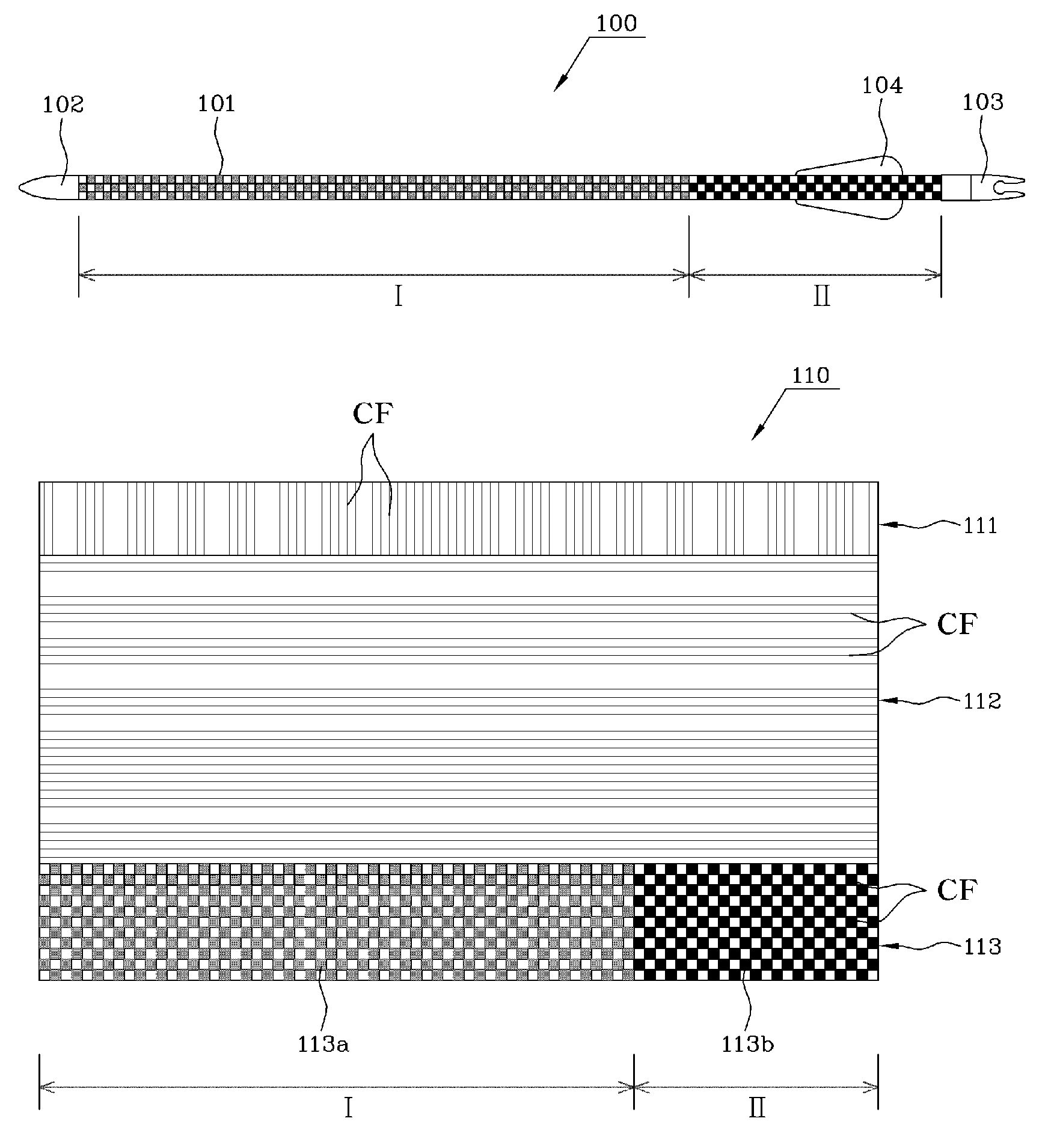
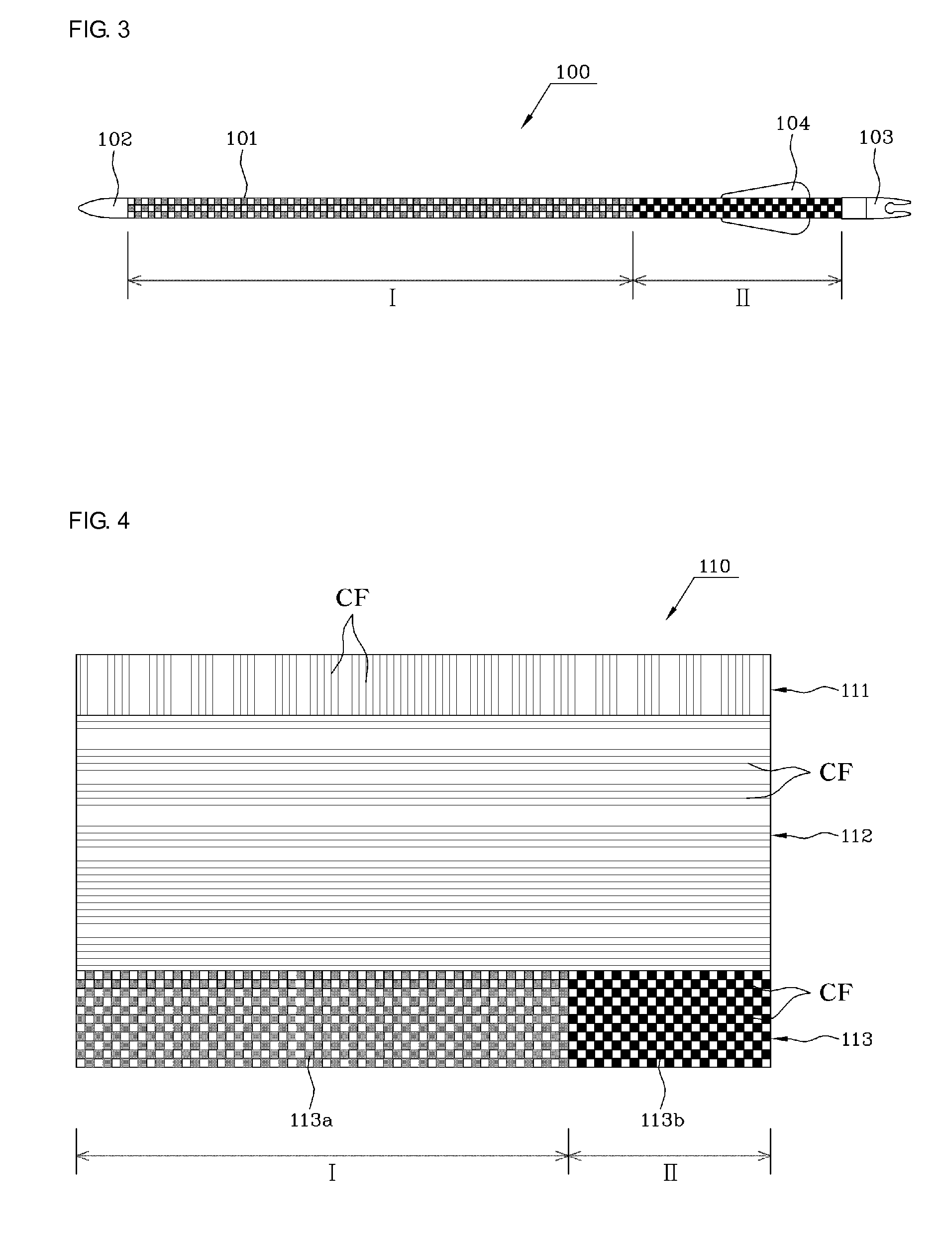
[0048]The present invention relates to an arrow shaft which is fabricated by dividing the arrow shaft into two parts at a predetermined ratio in the longitudinal direction, and then by laminating and winding sheet layers suitable to each of the parts on a respective part, such that material performance and physical properties of the arrow shaft can be improved and thus the flight stability and straight advancing property of an arrow can be enhanced and the durability of the arrow shaft can be highly increased.

[0049]According to the present invention, a front end portion of the arrow shaft, which has an arrow head coupled thereto and is subject to most of the impact of hitting a target, and a middle portion of the arrow shaft, which is likely to be weakened by the repeated occurrence of the archer's paradox phenomenon during the flight of the arrow, are reinforced. In addition, the strength and elasticity of a rear end portion of the arrow shaft, which is repeatedly subject to impact...


PUM


Abstract

Provided is an arrow shaft having a front and rear two stage spine structure and including a front end to which an arrowhead is coupled and a rear end to which a nock is coupled, wherein the arrow shaft has a hollow tubular shape and is divided and defined into a front part and a rear part in a longitudinal direction thereof such that spine strengths of the arrow shaft are different between the front part including a center of gravity of the arrow shaft and the rear part to which the nock is coupled; wherein the front and rear parts of the arrow shaft are formed by an arrow shaft shaping sheet constituted of three layers; wherein an uppermost layer of the arrow shaft shaping sheet includes a front sheet and a rear sheet respectively formed of a carbon fabric sheet each having different elastic strengths.

Description

BACKGROUND OF THE INVENTION[0001]1. Field of the Invention[0002]The present invention relates, in general, to an arrow shaft, and more particularly to an arrow shaft having a structure divided into two parts each having different spine strengths in a longitudinal direction of the arrow shaft, so that a deformation or fracture of the center of gravity of the arrow shaft due to an archer's paradox phenomenon necessarily occurring during flight of an arrow can be inhibited, a splitting of the arrow shaft due to impact applied to the arrow shaft upon shooting can be prevented, shooting accuracy of the arrow shaft can be increased, and partial deformation or fracturing of the arrow shaft due to frequent shooting can be prevented.[0003]2. Description of the Related Art[0004]FIG. 1 is a schematic view showing a conventional arrow shaft according to the related art.[0005]In general, arrows include an arrow shaft 11 having a hollow cylinder shape, an arrowhead 12 on a front end of the arrow ...

Claims


Application Information

Patent Timeline
Patent Type & Authority Patents(United States)
IPC IPC(8): F42B6/04
CPCF42B6/04F41B5/00
Inventor SONG, IN GYU
Owner SONG JIN HEE
Learn More