Dual mode automated intraocular lens injector device

a technology of injector device and intraocular lens, which is applied in the field of devices for delivering intraocular lens into the eye, can solve the problems of inconsistent injection force and displacement of syringe-type injector, poor visual quality, cumbersome and tedious, etc., and achieves minimal increase in injection resistance, enhanced tactile resistance feedback, and normal feedback of resistance.

Active Publication Date: 2013-11-12
ALCON INC
View PDF223 Cites 8 Cited by
  • Summary
  • Abstract
  • Description
  • Claims
  • Application Information

AI Technical Summary

Benefits of technology

[0014]A lever or command can be effective to mechanically disengage the powering drive mechanism from the lens injecting plunger, removing in this way the resistance required to manually slide the clutching mechanism. This action restores the normal feedback of resistance provided to the fingers of the operator when using the injector in manual mode of operation.
[0015]An overrunning clutch or freewheel mechanism can be incorporated to the injector power transmission mechanism allowing manual override of the powered drive mechanism with minimal increase in injection resistance when operating in the direction of injection, providing enhanced tactile resistance feedback during manually assisted lens injection. With this mechanism, the driving motor always becomes engaged in backward operation and manual drive is always required to retract the plunger, typically requiring disengagement of a torque limiter for plunger retraction.
[0016]When using selected powering motors such as those known as “direct drive” without a gearbox, there is no need for a disengage mechanism for manual operation, as the resistance added to manually activate the unpowered motor is negligible. However, the absence of a mechanical clutching mechanism imposes the need of an electronic fault detection system to detect increased resistance during operation.
[0020]The powering mechanism can be detachably coupled to the injector body in a way that when coupled motor power can be effectively transmitted to the plunger to operate both in powered and manual mode, but also allowing the injector to operate in manual-only modality when the powering mechanism is detached.

Problems solved by technology

When age or disease causes the lens to become less transparent, vision deteriorates because of the diminished light which can be transmitted to the retina.
However, threaded-type manual injectors require the use of two hands, which is cumbersome and tedious.
Syringe-type injectors produce inconsistent injection force and displacement.

Method used


Image

  • Dual mode automated intraocular lens injector device
  • Dual mode automated intraocular lens injector device
  • Dual mode automated intraocular lens injector device

Examples


Embodiment Construction

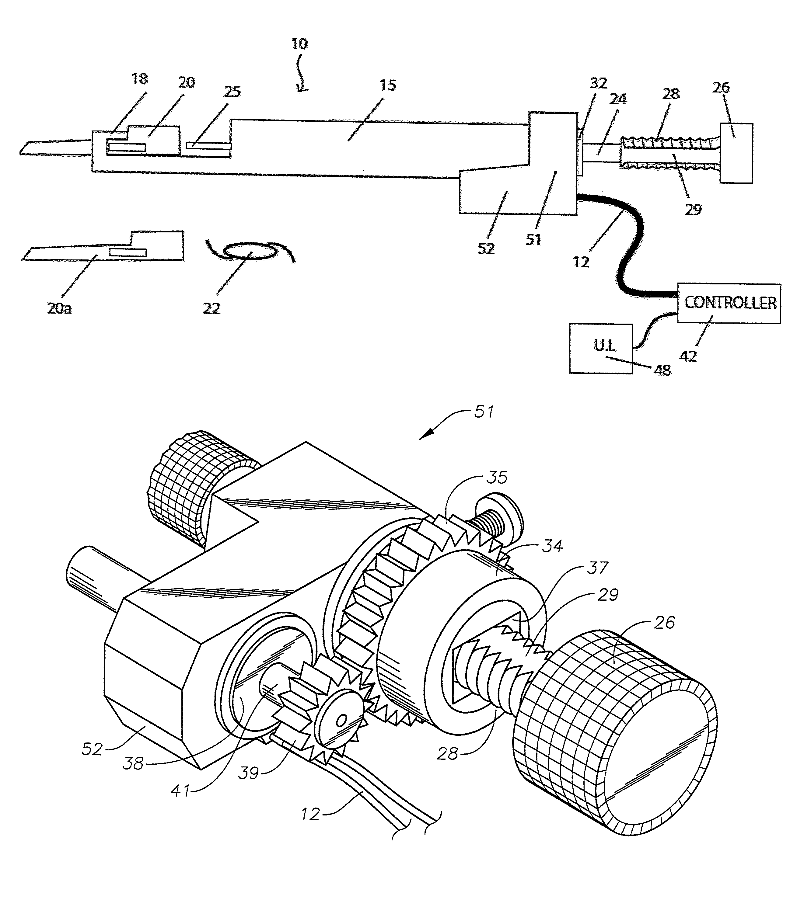
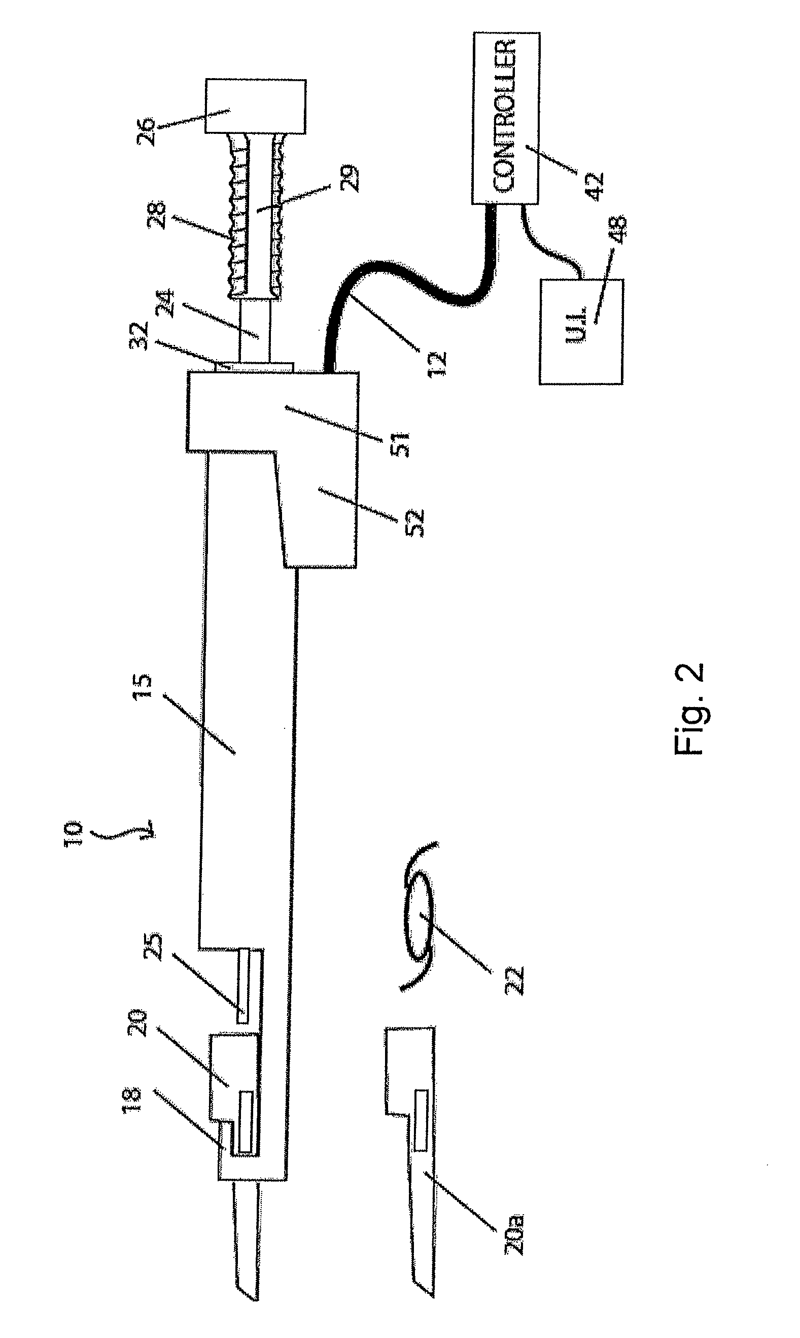
[0034]Reference is now made in detail to the exemplary embodiments of the invention, examples of which are illustrated in the accompanying drawings. Wherever possible, the same reference numbers are used throughout the drawings to refer to the same or like parts.

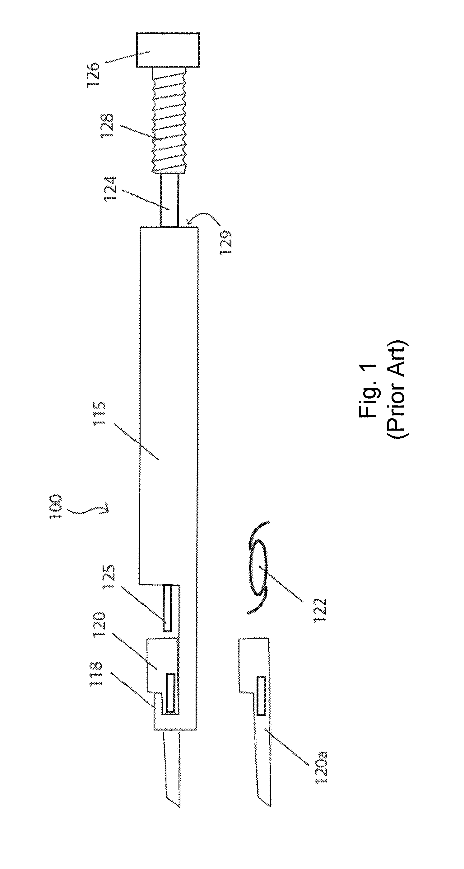
[0035]FIG. 1 illustrates a handheld intraocular lens (IOL) injection device of the prior art 100 for implanting an IOL into the anterior capsule of the eye. The IOL injection device 100 also comprises a cartridge mount 118, which holds a removably mounted insertion cartridge 120 typically press fitted into position. Injection cartridge 120 is usually a disposable polymeric component adapted to accommodate an unfolded IOL lens 122 and to fold and displace the lens as a plunger tip 125 is translated forward from a body 115 of injector 100 and through the insertion cartridge 120.

[0036]An operator counter rotates a knob 126 until a male thread 128 is released from a receiving female thread 129 fixedly disposed inside injector ho...


PUM


Abstract

An IOL injector device allows for both powered and manual delivery of an IOL. The injector has a tubular housing. A plunger is longitudinally disposed within the housing and has first and second ends. The first end is disposed towards the front end of the housing. A drive system is coupled to the housing. The drive system causes longitudinal translation of the plunger along the primary axis of the housing. A normally engaged clutch system is coupled to the drive system. The normally engaged clutch system allows manual disengagement of the drive system. A knob coupled to the plunger allows for manual operation of the injector.

Description

[0001]This application claims the benefit of U.S. Provisional Patent Application No. 61 / 367,440 filed Jul. 25, 2010.BACKGROUND OF THE INVENTION[0002]The present invention relates generally to a device for delivering an intraocular lens into an eye. The device has both a powered modality of operation and a manual modality of operation. The manual modality of operation may at any time override the powered modality of operation while providing the same accuracy and safety of known manual threaded lens delivering devices.[0003]The human eye functions to provide vision by transmitting light through a clear outer portion called the cornea, and focusing the image by way of a crystalline lens onto a retina. The quality of the focused image depends on many factors including the size and shape of the eye, and the transparency of the cornea and the lens. When age or disease causes the lens to become less transparent, vision deteriorates because of the diminished light which can be transmitted ...

Claims


Application Information

Patent Timeline
Patent Type & Authority Patents(United States)
IPC IPC(8): A61F2/16
CPCA61F2/1662A61F2/1672
Inventor ZACHARIAS, JAIME
Owner ALCON INC
Why Eureka
Try Eureka