
Method, system, and system components for wireless tire pressure monitoring

a tire pressure monitoring and wireless technology, applied in vehicle tyre testing, roads, instruments, etc., can solve the problems of increasing the complexity of the receiving antenna, requiring a certain level of complexity, and requiring a relatively low transmission rate of data, so as to achieve quick and easy determination

Active Publication Date: 2013-11-12
HUF BAOLONG ELECTRONICS BRETTEN GMBH
View PDF16 Cites 1 Cited by
  • Summary
  • Abstract
  • Description
  • Claims
  • Application Information

AI Technical Summary

Benefits of technology

The present invention proposes a method and system for monitoring and wirelessly signaling data from wheel electronics units in a vehicle. The method reduces the power requirement of the wheel electronics units by reducing the amount of data transmitted in a burst mode. The data is transmitted in two modes: a driving mode and a starting mode. In the driving mode, a longer burst of data is transmitted, while in the starting mode, a shorter burst of data is transmitted to avoid data loss. The data is transmitted in the form of shortened datagrams, which are accumulated during the transmission duration to ensure safe reception by the controller. The controller can determine the position of the wheel based on the received field strengths and the direction of rotation of the wheel. This allows for specific and easy determination of the wheel's position.

Problems solved by technology

While it is possible in this way to specifically address the individual wheel electronics units in the wheels in order to detect the exact position allocation of the wheels, for example, this solution requires a certain level of complexity.
However, the data would then only be transmitted at a relatively low transmission rate.
This solution thus can completely forego a trigger system, however greater complexity is required on the part of the receiving antennas.
Furthermore, a method is known which utilizes a duty cycle of 50% LF in standstill and 100% in driving operation, resulting the corresponding energy consumption.

Method used


Image

  • Method, system, and system components for wireless tire pressure monitoring
  • Method, system, and system components for wireless tire pressure monitoring
  • Method, system, and system components for wireless tire pressure monitoring

Examples


Embodiment Construction

[0029]Before FIGS. 1 and 2 and the method according to the invention will be addressed in more detail, first the basic design of the system according to the invention will be explained based on FIGS. 3 and 4.

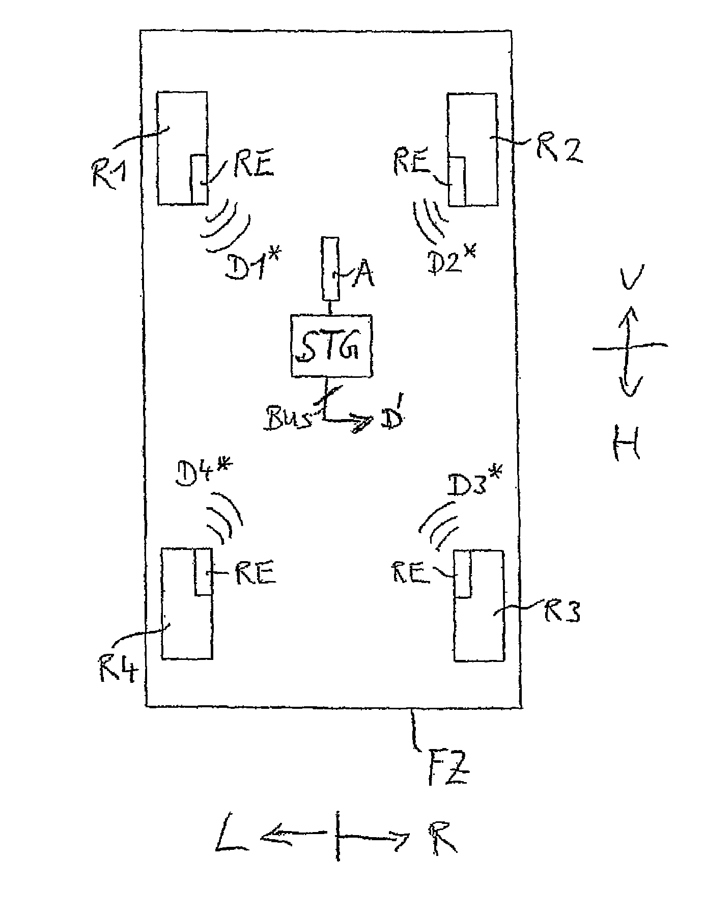
[0030]FIG. 3 shows the basic design and / or the installation of a system in a vehicle FZ, wherein electronic modules or wheel electronics units RE are inserted in the individual wheels R1 to R4 of the vehicle, which wirelessly transmit the data thereof D1* to D4* to a controller STG, which is disposed in the vehicle as a central control unit.

[0031]The controller STG is connected to a wireless receiving means in the form of an antenna A in order to receive the radio signals of the individual wheel electronics units RE and evaluate the data contained therein. The controller STG is connected to further devices and / or modules (not shown) by way of a data interface or a data bus and supplies these with results data D′ obtained from the evaluation of the received data D1* to D4* and op...


PUM


Abstract

Disclosed is a method for monitoring and wirelessly signaling data that contains information on the pressure states prevailing in tires of wheels of a vehicle. In the method, electronic modules that are arranged in the wheels wirelessly transmit the data to control device which is arranged in the vehicle. No data is transmitted during a first mode associated with a standstill state of the vehicle, while the respective electronic module transmits the data to the control device in the form of telegrams, during at least one other mode associated with another state of the vehicle. The respective electronic module at least temporarily transmits n telegrams containing the data per time unit to the control device, n being a function of time.

Description

[0001]The invention relates to a method for monitoring and wirelessly signaling data containing information about the pressure conditions present in the pneumatic tires of wheels of a vehicle.[0002]The invention further relates to a system suited therefor, to system components, such as a controller which is disposed in the vehicle, and an electronic module which is disposed in one of the wheels and wirelessly transmits data to the controller.[0003]The article “Tyre Safety Systems—TSS” from February 2005, published in “automobiltechnische Zeitschrift (ATZ)” (edition 2 / 2005, VIEWEG publishing house, Germany), describes tire pressure control systems, wherein a variety of data containing information about the conditions present in pneumatic tires of wheels of a vehicle is monitored and wirelessly signaled. As is described in the article based on illustrations 3 and 4, such a known system comprises a plurality of electronic modules, which are disposed in the wheels of the vehicle and are...

Claims


Application Information

Patent Timeline
Patent Type & Authority Patents(United States)
IPC IPC(8): B60C23/00
CPCB60C23/0416B60C23/0462
Inventor WAGNER, MARKUS
Owner HUF BAOLONG ELECTRONICS BRETTEN GMBH
Features
  • Generate Ideas
  • Intellectual Property
  • Life Sciences
  • Materials
  • Tech Scout
  • Unparalleled Data Quality
  • Higher Quality Content
  • 60% Fewer Hallucinations
Learn More