
Impedance-scanning quartz crystal microbalance

a quartz crystal and microbalance technology, applied in the field of impedance-scanning quartz crystal microbalance, can solve the problems of reducing the accuracy of the frequency, reducing the quality of the oscillator, and reducing the speed of the measurement, so as to achieve the effect of reducing the cost, reducing the cost, and reducing the cos

Inactive Publication Date: 2013-11-12
C3 PROZESS & ANALYZENTECHN
View PDF5 Cites 0 Cited by
  • Summary
  • Abstract
  • Description
  • Claims
  • Application Information

AI Technical Summary

Benefits of technology

The patent aims to provide a better method and device for detecting changes in mass in real-time and in-situ measurements. The new method and device overcome some of the limitations of previous methods.

Problems solved by technology

Extensions to encompass the entire shift of the phase position so that a phase shift through 0° takes place again are complicated and subject to error.
It is also often necessary to compensate manually for parasitic capacitance, which is disadvantageous especially when the goal is to perform efficient, automated measurements.
Parasitic and unavoidable phase shifts caused by the electronic layout also contribute to a decrease in the accuracy of the frequency—the quality of the oscillator is reduced.
The disadvantage of this method is that the measurements proceed very slowly, and in some cases several seconds are required per measurement point.
This makes in-situ and real-time measurements impossible, especially when several thousand measurement points must be measured to obtain, for example, highly resolved frequency data.
Fitting to the BvD model, furthermore, is highly unreliable and slow because of the methodology of nonlinear approximation.
When there are up to ten parameters to be fitted and up to 100,000 measurement points, the process takes a great deal of time.
In some cases the fit converges poorly or not at all.
The quality of the result, furthermore, is very poor.
The starting parameters required are very difficult to estimate, because variables which are difficult if not impossible to observe experimentally are contained in them.
This method therefore makes available a large number of interpretable electrical parameters, but it is difficult or impossible to use it to obtain rapid in-situ measurements.

Method used


Image

  • Impedance-scanning quartz crystal microbalance
  • Impedance-scanning quartz crystal microbalance
  • Impedance-scanning quartz crystal microbalance

Examples


Embodiment Construction

[0066]Reference will now be made in detail to the present embodiments of the present invention, examples of which are illustrated in the accompanying drawings, wherein like reference numerals refer to the like elements throughout. The embodiments are described below in order to explain the present invention by referring to the figures.

[0067]In comparison with the measuring devices known from the prior art, several crucial changes and simplifications are proposed. Phase data are not read out, which greatly simplifies the design. Magnitude data are recorded in proprietary relative units. The quartz crystal is connected to the measuring device in such a way that it is completely isolated from DC voltage, which makes it possible to perform electrochemical measurements (EQCM) without interference. Standards are thus set especially in regard to measuring speed. Thus the unit is connected to the computer by way of a USB interface. The hardware is so highly optimized that a data recording r...


PUM


Abstract

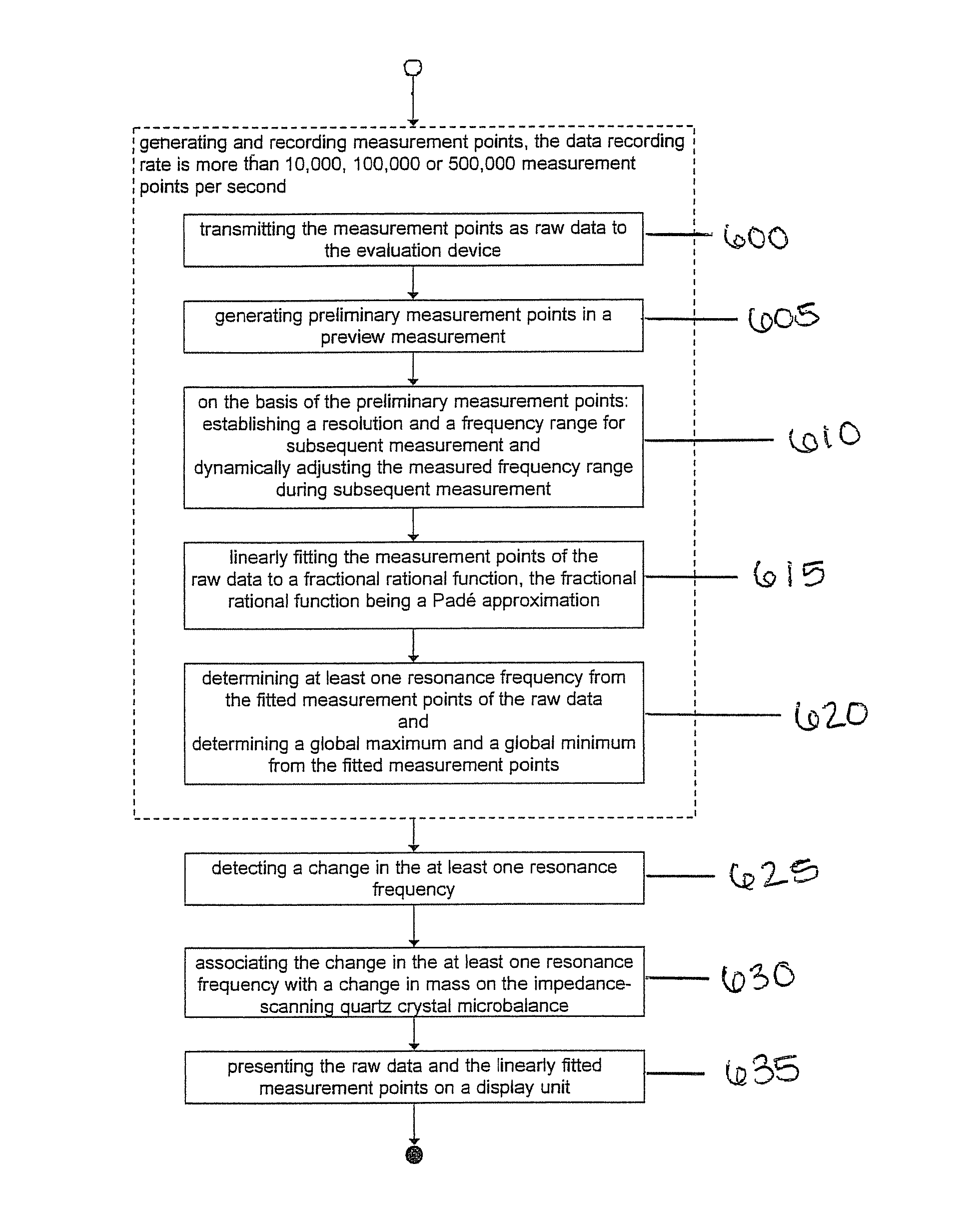
Method for detecting a change in mass with a quartz crystal impedance-scanning microbalance, which can be connected to an evaluation device, wherein the quartz crystal microbalance is designed to transmit the measurement points recorded at a predetermined data recording rate as raw data to the evaluation device, including at least the following steps: linearly fitting the measurement points of the raw data to a fractional rational function and determining at least one resonance frequency from the fitted measurement points of the raw data, wherein a change in the at least one resonance frequency corresponds to an effective change in mass.

Description

CROSS-REFERENCE TO RELATED APPLICATIONS[0001]This application is a national stage application of PCT Application No. PCT / EP2008 / 065248, filed Nov. 10, 2008, in the European Intellectual Property Office, and claims priority to German Application Number DE 10 2007 053 573,4, filed Nov. 9, 2007, the disclosures of which are incorporated herein by reference.BACKGROUND OF THE INVENTION[0002]1. Field of the Invention[0003]The invention pertains to a method for detecting a change in mass with an impedance-scanning quartz crystal microbalance and to a device for detecting a change in mass.[0004]2. Description of the Related Art[0005]Quartz crystal microbalances (QCM) are known from the prior art as a means of detecting extremely small changes in mass. The core element of a quartz crystal microbalance is a quartz resonator, which can be caused to vibrate at a resonance frequency by the application of an alternating voltage. Because of the high quality of quartz resonators and the associated ...

Claims


Application Information

Patent Timeline
Patent Type & Authority Patents(United States)
IPC IPC(8): G01Q30/00G05B5/00G01G9/00G01D21/00G06F19/00G06F17/40
CPCG01G3/13G01G3/16
Inventor WUDY, FRANZMULTERER, MICHAELSCHMEER, GEORGGORES, HEINER JACOB
Owner C3 PROZESS & ANALYZENTECHN
Learn More