Multi-port stopcock valve and flow designating system

a technology of flow designating system and stopcock valve, which is applied in the direction of service pipe system, mechanical equipment, transportation and packaging, etc., can solve the problems of difficulty and error in determining the functionality of the prior art stopcock at any given “setting, and inability to allow fluid flow, etc., to achieve simple manufacturing, simplify complex fluid flow arrangement system, and maintain ease of use and safety

Active Publication Date: 2013-11-19
MONUMEDICAL
View PDF40 Cites 26 Cited by
  • Summary
  • Abstract
  • Description
  • Claims
  • Application Information

AI Technical Summary

Benefits of technology

[0013]Uniquely with this invention, a pair of indicator portions are provided including a first indicator portion and a second indicator portion relating to stopcock operational status. These first and second indicator portions interact with each other to provide this operational status information. One of the indicator portions includes markings generally aligned with the fluid conveyance ports joined to the valve body. The second indicator portion includes a visual barrier which is coupled to the central hub so that the second indicator portion rotates with the central hub. This visual barrier is configured to block markings of the first indicator which are closed and not block markings on the first indicator which correspond with ports which are open. In a preferred form of this invention, the second indicator portion is in the form of a plate with fenestrations therein that are generally aligned with the ends of the fluid flow paths in the central hub. Thus, when these ends of the flow paths of the central hub are aligned with the ports, the fenestrations in the rotating fenestrated plate are aligned with the markings of the first indicator portion, so that the markings can be seen by a user. The user sees a marking adjacent each port which is open and no mark next to each port which is closed. The user can thus readily determine which ports are open and which ports are closed and hence which ports are delivering or receiving fluid within the system in which the stopcock is located.
[0024]Another object of the present invention is to provide a stopcock which can be of simple manufacture and formed of low cost materials, such as by utilization of injection molded plastics.

Problems solved by technology

All prior art stopcocks, including those listed above are fraught with less than adequate demarcations or indications for whether a given port is in the open or closed position.
This problem yields difficulty and error in determining the functionality of the prior art stopcock at any given “setting.”
This single sided central port only communicates with the outer ports, and does not allow for fluid flow all the way through the hub.
Loo's stopcock functionality is very hard to interpret making it difficult to know which ports are open and which are closed.
His designs include two separate non-mixing fluid paths which increases the complexity and chance for medication errors, particularly so with the lack of an adequate flow designation system.

Method used


Image

  • Multi-port stopcock valve and flow designating system
  • Multi-port stopcock valve and flow designating system
  • Multi-port stopcock valve and flow designating system

Examples


Embodiment Construction

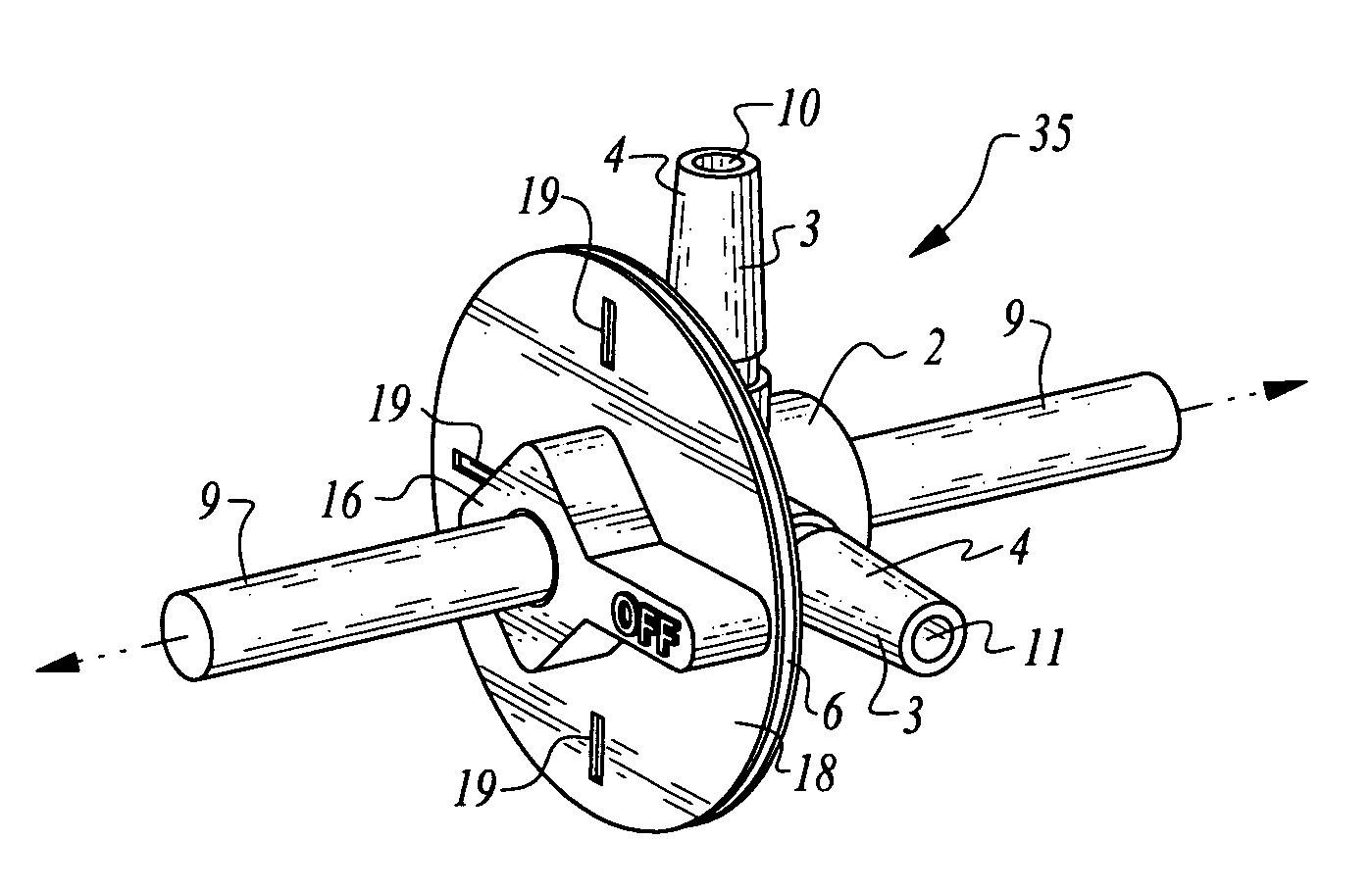
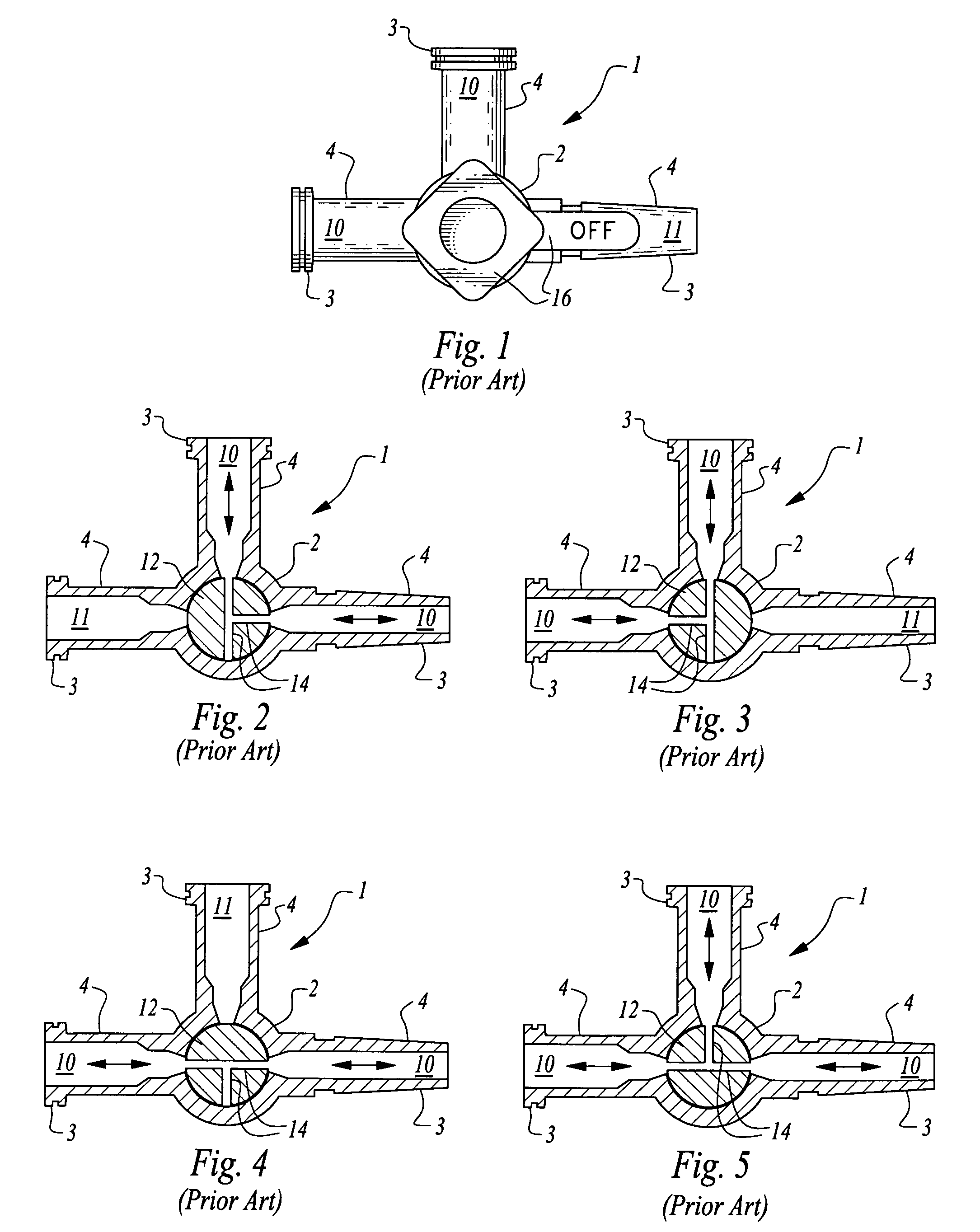
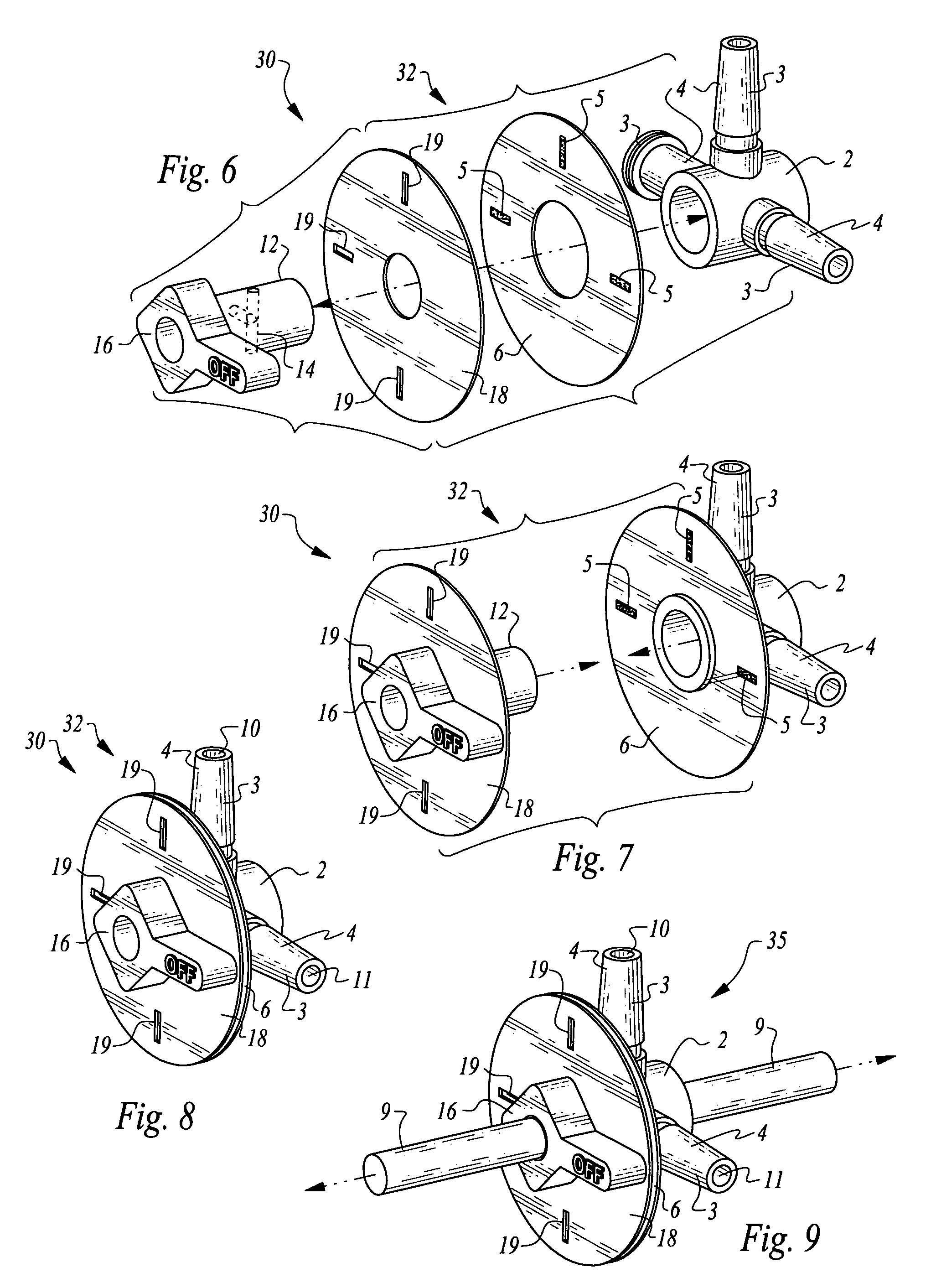
[0041]Referring to the drawings, wherein like reference numerals represent corresponding related parts throughout the various drawing figures, reference numeral 1 is directed to a prior art stopcock (FIGS. 1-5). This prior art stopcock 1, as well as the various stopcocks 20, 30, 40, 50, 60, 70, 80, 90 of this invention (FIGS. 6-95) share many common attributes, as well as important distinctions, elucidated herein through reference to exemplary embodiments depicted herein. Through manipulation of these stopcocks, various different fluid conveyance ports 4 joined to a valve body 2 can be either opened or closed for fluid flow therethrough, such as indicated by flow arrows on the drawings associated with the different embodiments. For each embodiment, different views are provided to show the various different positions of a central hub 12 relative to the valve body 2, as well as relative positions of a fixed plate 6 relative to a rotating fenestrated plate 18 which quickly and easily i...


PUM


Abstract

A stopcock is provided with multiple ports joining multiple fluid conduits leading between fluid sources and fluid destinations. A central hub manifold resides within a valve body supporting the ports, and can rotate relative to the valve body. Fluid flow paths within the central hub are selectively aligned or not aligned with the ports. The stopcock indicates which ports are open by providing marks corresponding with positions of the ports. When the marks are visible, the corresponding ports are open. With different positioning of ports and different configurations of fluid flow paths within the central hub, stopcocks having different numbers of operable positions are provided including two, three, four, six and eight way stopcocks. By providing an axial flow path through a central axis of the central hub intersecting the embedded fluid flow paths within the central hub, still further numbers of operational states are provided.

Description

CROSS-REFERENCE TO RELATED APPLICATIONS[0001]This application claims benefit under Title 35, United States Code §119(e) of U.S. Provisional Application No. 61 / 271,422 filed on Jul. 20, 2009.FIELD OF THE INVENTION[0002]The following invention relates to stopcock type valves for opening and closing fluid pathways. More particularly, this invention relates to stopcocks such as those used in the scientific and medical fields for routing fluids or medication (medicament) into tubing, a device, multiple devices, a patient or any combination thereof. These stopcocks allow for control of fluid flow between various different sources and destinations within a given system.BACKGROUND OF THE INVENTION[0003]In the scientific fields it is often necessary to manipulate fluid flow through conduits by opening, closing and diverting fluid flow to transport or mix various fluids from various sources. The most common example of this occurs in medicine where medicament (medication or fluid) infusing int...

Claims


Application Information

Patent Timeline
Patent Type & Authority Patents(United States)
IPC IPC(8): F16K37/00F16K11/07A61M5/175
CPCF16K11/0853F16K37/0008A61M39/223A61M2039/229Y10T137/8275Y10T137/8259Y10T137/8309Y10T137/86871
Inventor DUNCAN, DAVID R.
Owner MONUMEDICAL
Why Eureka
Try Eureka