Ophthalmologic photographing apparatus

a technology of ophthalmologic photography and apparatus, applied in the field of ophthalmologic photography apparatus, can solve the problems of difficult to obtain correct focus and poor visibility of subjects, and achieve the effect of excellent visibility

Inactive Publication Date: 2013-11-19
CANON KK
View PDF11 Cites 20 Cited by
  • Summary
  • Abstract
  • Description
  • Claims
  • Application Information

AI Technical Summary

Benefits of technology

[0012]The present invention is directed to an ocular fundus observation apparatus which can select a color of an alignment index which is excellent in visibility to an observation light source when the observation light source is changed and can obtain a suitable focal state to the selected color.

Problems solved by technology

Thus, it becomes difficult to obtain correct focus.
Even if this method can be recognized by an examiner, visibility is hardly excellent for a subject.

Method used


Image

  • Ophthalmologic photographing apparatus
  • Ophthalmologic photographing apparatus
  • Ophthalmologic photographing apparatus

Examples


Embodiment Construction

[0025]Various exemplary embodiments, features, and aspects of the invention will be described in detail below with reference to the drawings.

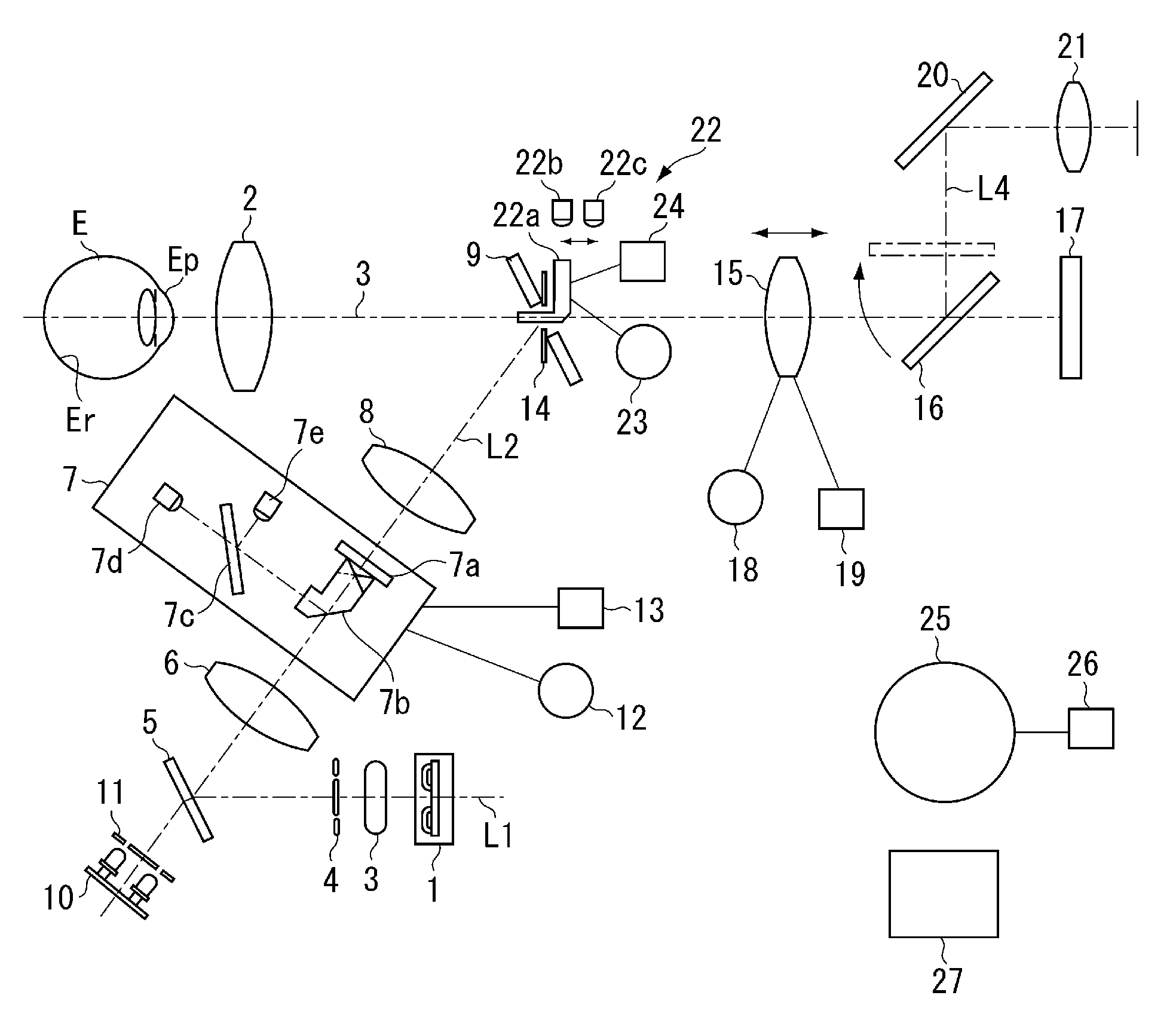
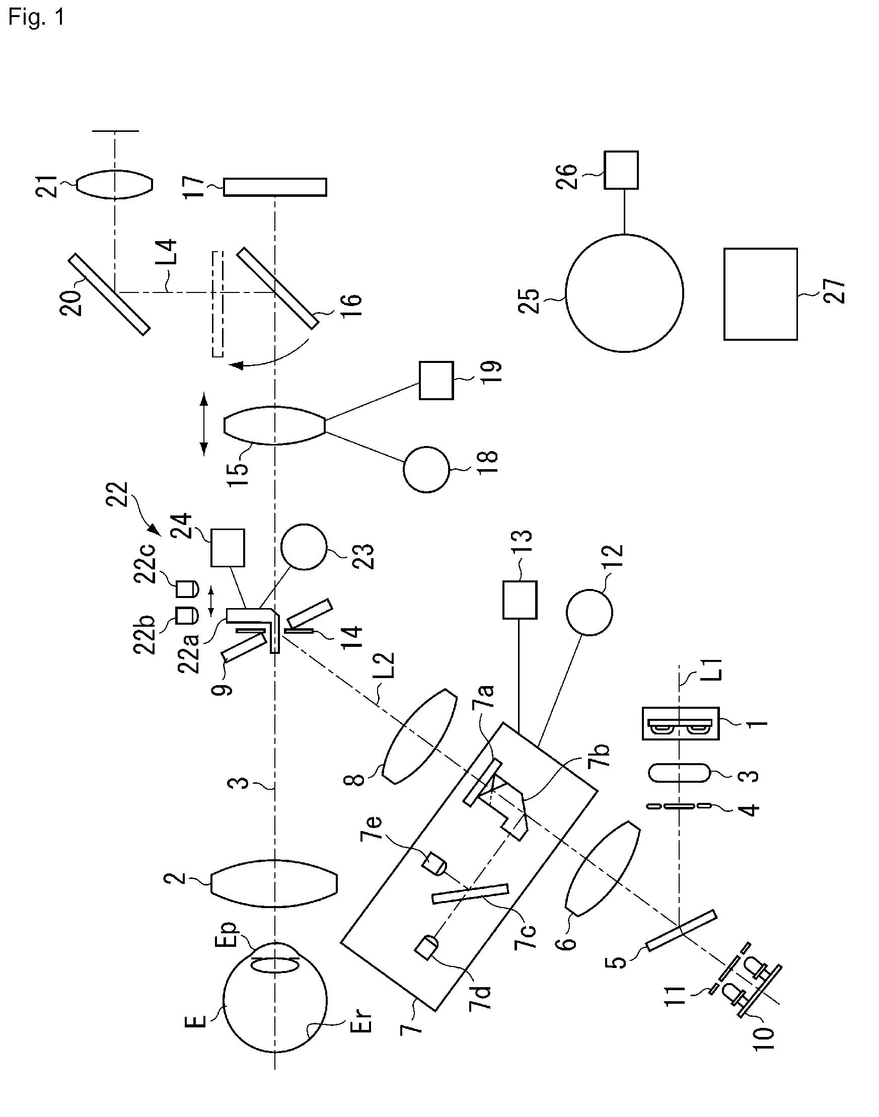
[0026]FIG. 1 is a block diagram illustrating a fundus camera according to a first exemplary embodiment. In an illumination optical system from a halogen lamp 1 to an objective lens 2 disposed in front of an eye to be examined E, the halogen lamp 1 as an observation light source, a xenon lamp 3 as a photographing light source, a visible light ring slit 4, and a dichroic mirror 5 are arranged on an optical path L1. Further, on an optical path L2 on the reflection side of the dichroic mirror 5, a relay lens 6, a prism unit 7, a relay lens 8, and a perforated mirror 9 are arranged. Furthermore, in a direction coaxial with the optical path L2 in the rear of the dichroic mirror 5, an infrared light emitting diode (LED) 10 as an observation light source and an infrared ring slit 11 are provided.

[0027]The halogen lamp 1 is a first observation light sou...


PUM


Abstract

When an observation state by an infrared LED 10 is changed to a photographing state by a xenon lamp 3, a movable mirror 16 is pulled upward and an optical path is switched to an image sensor 17 side. A light guide 22a is shifted by an alignment index drive motor 23 so that an incident portion of an alignment index is shifted from a visible LED 22b to direct to an infrared LED 22c. An outgoing portion of the light guide 22a is set at a position where an image is formed on the image sensor 17 by a wavelength of the infrared LED 22c when an operation distance is appropriate. While changing a luminescent color, a position of a luminescent point of the alignment index is changed by switching the LED by the shift of the light guide 22a.

Description

TECHNICAL FIELD[0001]The present invention relates to an ocular fundus observation apparatus which can change an observation light source between infrared light and visible light to perform observation.BACKGROUND ART[0002]In recent years, a mydriatic / non-mydriatic combination type fundus camera has been used in an ocular fundus observation apparatus, particularly in a fundus camera, to reduce a burden of a subject as much as possible. The mydriatic / non-mydriatic combination type fundus camera can perform mydriatic photographing and non-mydriatic photographing corresponding to contents of examination by one fundus camera.[0003]Generally, infrared light is used in observation before non-mydriatic photographing, and visible light is used in observation before mydriatic photographing. In Japanese Patent Application Laid-Open No. 7-100112, it is discussed that visible light and infrared light are selectively used as an observation light source of an eye to be examined and a wavelength of...

Claims


Application Information

Patent Timeline
Patent Type & Authority Patents(United States)
IPC IPC(8): A61B3/14A61B3/10
CPCA61B3/152
Inventor AIKAWA, SATOSHIOOBAN, HIDEYUKIIWANAGA, TOMOYUKIMASAKI, TOSHIFUMI
Owner CANON KK
Why Eureka
Try Eureka