Video projector which obliquely projects images onto screen

a projector and video technology, applied in the field of video projectors, can solve the problems of difficult reduction of the required torque for rotating the mirror, difficulty in reducing the size and weight of the video projector, etc., and achieve the effect of reducing the length of the arm of the mirror rotator, and reducing the size of the mirror

Active Publication Date: 2013-11-19
MAXELL HLDG LTD
View PDF3 Cites 3 Cited by
  • Summary
  • Abstract
  • Description
  • Claims
  • Application Information

AI Technical Summary

Benefits of technology

[0008]In view of the above problems, an object of the invention is thus to reduce the size and weight of a video projector by shortening the length of the arm of a mirror rotator and reducing the size of a mirror.
[0012]In accordance with the invention, the size and weight of a video projector can be reduced by the length of the arm of a mirror rotator being reduced and the size of a mirror being reduced.

Problems solved by technology

Projectors that involve the use of a reflective mirror, such as the one in Japanese Unexamined Patent Application Publication No. 2006-259252, are disadvantageous in the following respects.
Because of this, it has been quite difficult to reduce the size and weight of a video projector.
Reducing the required torque for rotating the mirror has also been difficult because of the difficulty in reducing the mirror size.

Method used


Image

  • Video projector which obliquely projects images onto screen
  • Video projector which obliquely projects images onto screen
  • Video projector which obliquely projects images onto screen

Examples


Embodiment Construction

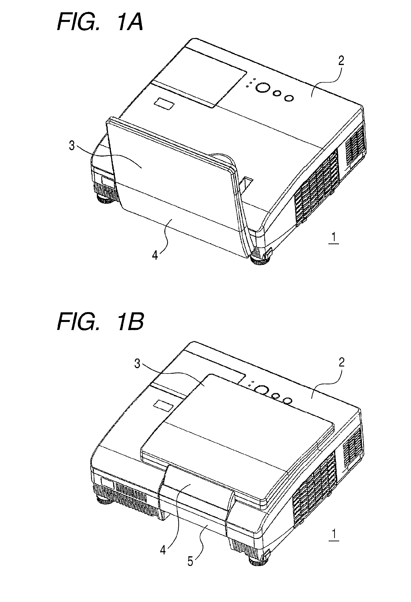
[0020]FIGS. 1A and 1B are perspective views of a video projector according to an embodiment of the invention. FIG. 1A illustrates the state of the projector when its reflective mirror is open, and FIG. 1B illustrates its state when the reflective mirror is closed.

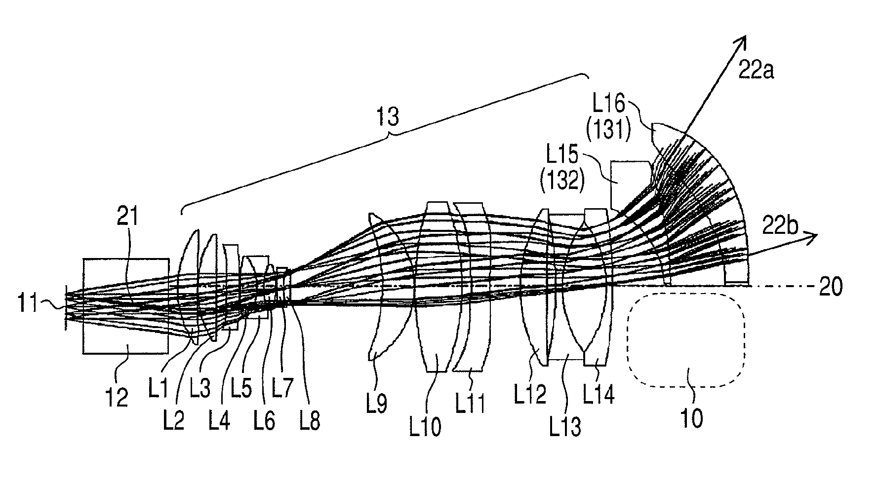
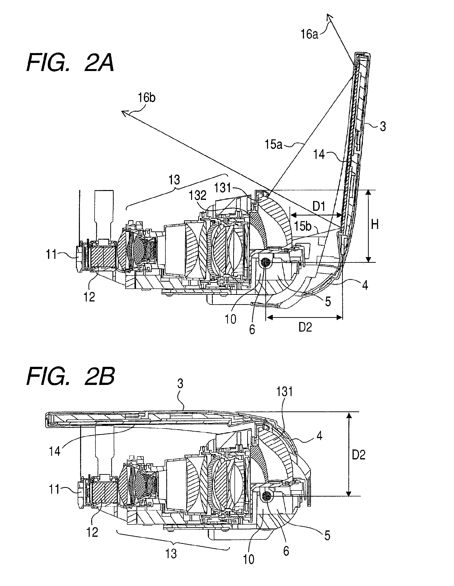
[0021]The video projector 1 of FIGS. 1A and 1B uses the reflective mirror to obliquely project images formed in its image display element (e.g., a reflective or transmissive liquid crystal panel) onto a projection screen or board, thereby displaying the images in a magnified manner. The image display element can be a micro-mirror device in which multiple micro-mirrors are arrayed (e.g., Digital Micromirror Device: trademark of Texas Instruments, Inc.). A housing 2 houses main components such as an optical projection system, an optical illumination system, and circuitry components. Attached to the top side of the housing 2 is a mirror support plate 3 that supports the reflective mirror. The mirror support plate 3 is secured ...


PUM


Abstract

An object of the invention is to reduce the size and weight of a video projector by shortening the length of the arm of a mirror rotator and reducing the size of a mirror. A video projector comprises a plurality of projection lenses through which image light rays from a liquid crystal panel are extracted in a magnified manner; a reflective mirror for reflecting the extracted image light rays onto a screen; and a mirror rotator for rotating the reflective mirror so that the extracted image light rays can be reflected in particular directions. Among the projection lenses, some of the projection lenses located farther away from the liquid crystal penal are partially cut such that areas through which the image light rays do not pass are cut off to create a lens cut-off space. The mirror rotator is placed in the lens cut-off space.

Description

CLAIM OF PRIORITY[0001]The present application claims priority from Japanese Patent Application No. 2009-222617, filed on Sep. 28, 2009, the content of which is hereby incorporated by reference into this application.BACKGROUND OF THE INVENTION[0002]1. Field of the Invention[0003]The present invention relates to a video projector that obliquely projects images formed in its image display element (e.g., liquid crystal panel) onto a projection screen or board, thereby displaying the images in a magnified manner.[0004]2. Description of the Related Art[0005]Such a video projector is required to project an adequately magnified image on a screen, and what is particularly required are that the shadow of the user should not be projected on the screen and that the user should be able to avoid directly seeing image light rays from the projector. For this reason, video projectors are now manufactured, which require a shorter distance to a screen. The optical projection system of such a video pr...

Claims


Application Information

Patent Timeline
Patent Type & Authority Patents(United States)
IPC IPC(8): G03B21/28G02B7/198
CPCG03B21/28
Inventor ONO, CHOHEIOGURA, NAOYUKIHIRATA, KOJIYATSU, MASAHIKOFUKUI, MASAYUKIKURACHI, MEGUMI
Owner MAXELL HLDG LTD
Why Eureka
Try Eureka