
Method and system for reducing ringing artifacts of image deconvolution

a technology of image deconvolution and artifact reduction, applied in image enhancement, image analysis, instruments, etc., can solve the problems of ringing artifacts occurring and other kinds of pictures failing, and achieve the effect of improving the reduction of ringing artifacts of image deconvolution

Inactive Publication Date: 2013-11-19
SONY CORP
View PDF16 Cites 7 Cited by
  • Summary
  • Abstract
  • Description
  • Claims
  • Application Information

AI Technical Summary

Benefits of technology

[0005]It is therefore an object of the present invention to reduce the disadvantages of the prior art. Specifically, it is an object of the present invention to provide a method and system for an improved ringing artifact reduction of image deconvolution.
[0010]According to a further aspect of the present invention there is provided a system for reducing ringing artifacts of image deconvolution, comprising

Problems solved by technology

However, with most image deconvolutions ringing artifacts occur as a side effect, in particular if the point spread function in the frequency domain has nulls.
However, according to prior art there are methods that work well for some types of pictures, but fail for other kinds of pictures.
For example there are methods which provide a good result in flat areas but encounter problems with texture areas in particular in regions where texture and strong image structure co-exist.

Method used


Image

  • Method and system for reducing ringing artifacts of image deconvolution
  • Method and system for reducing ringing artifacts of image deconvolution
  • Method and system for reducing ringing artifacts of image deconvolution

Examples


first embodiment

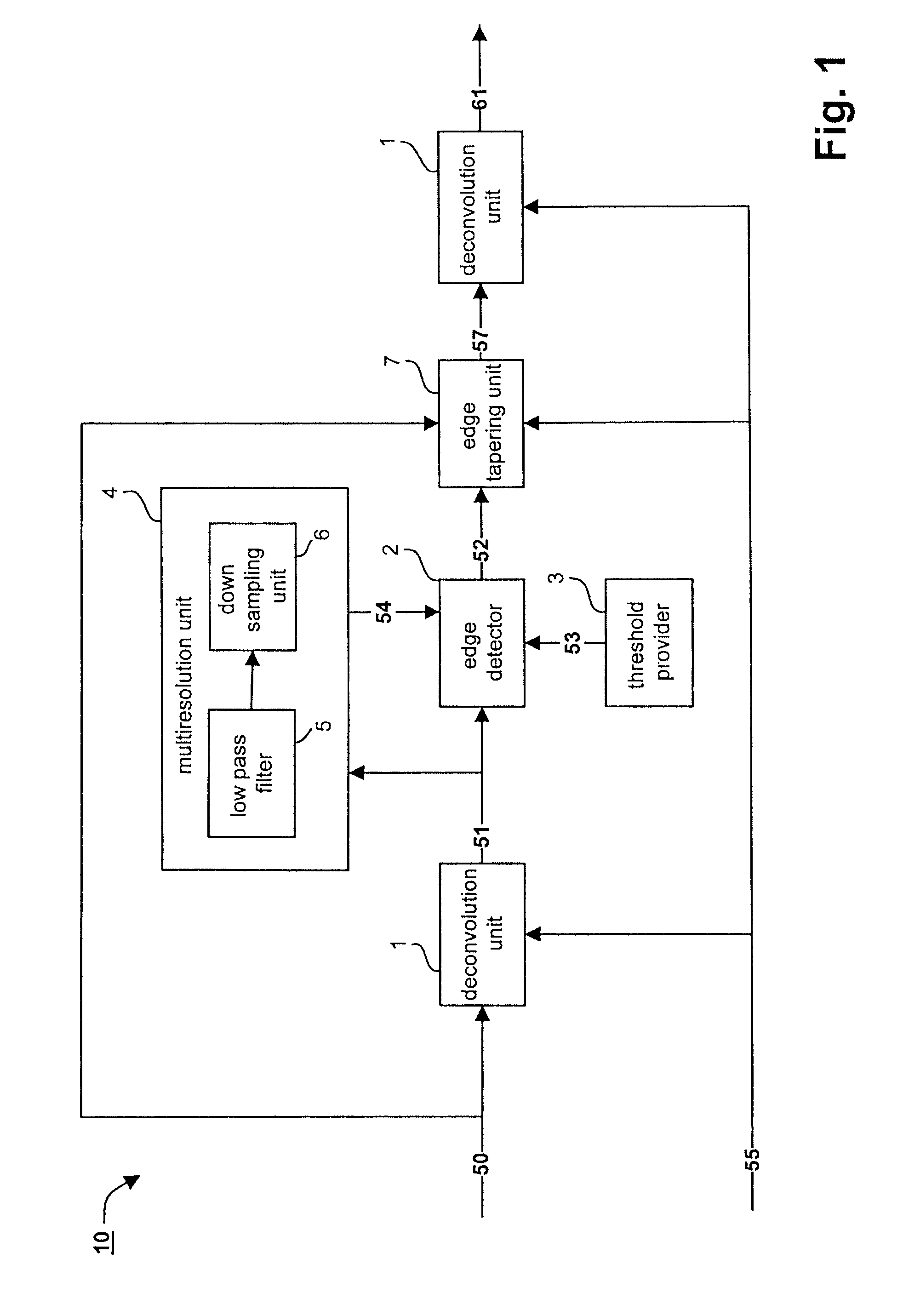
[0031]FIG. 1 shows a system 10 for reducing ringing artifacts according to the present invention.

[0032]The original blurred image 50 as well as the point spread function (PSF) 55 are submitted to a deconvolution unit 1. The deconvolution unit 1 is adapted to carry out a deconvolution on the original blurred image 50 or any other submitted image using the point spread function 55. As deconvolution any known or future deconvolution method can be used. The deconvolution can be iterative or non-iterative. Examples for the used deconvolution are the Van Cittert deconvolution, the Wiener deconvolution, the Richardson-Lucy deconvolution or any other known or future deconvolution method.

[0033]The deconvolved image 51 is then submitted to an edge detector 2. Further comprised in the system 10 is a threshold provider 3 which provides a threshold value 53 to the edge detector 2.

[0034]The edge detector 2 is adapted to use any known or future method of detecting edges using the threshold value 5...

second embodiment

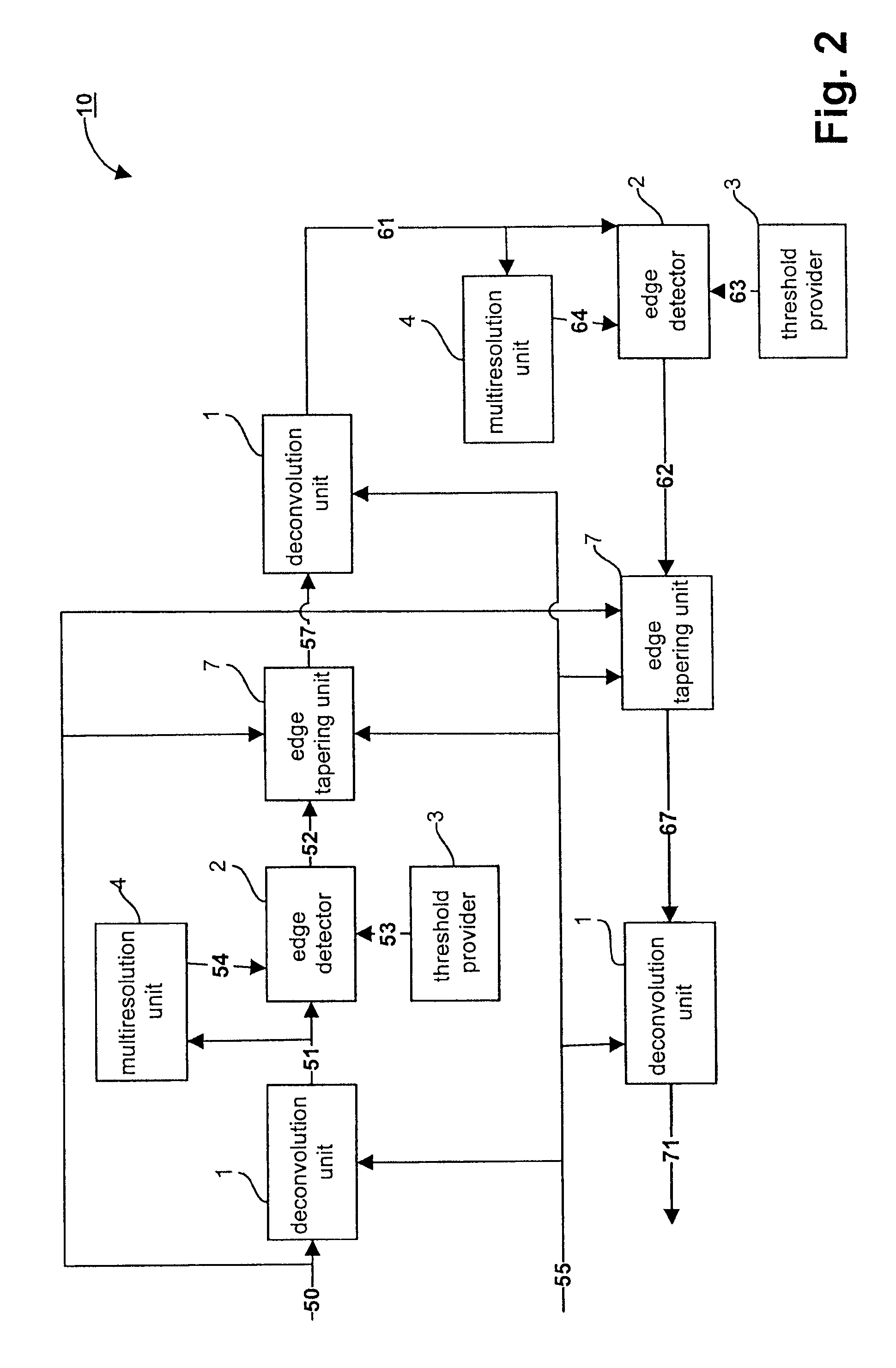
[0049]FIG. 2 shows a system for reducing ringing artifacts 10 according to the present invention.

[0050]It is again to be noted that even although components having the same reference numeral are shown several times in FIG. 2 for the sake of clarity, in a preferred embodiment these components are not separate components but they are implemented into one single component and only for the sake of clarity are shown as separate component in the figure.

[0051]The components and processes starting from the reception of the original blurred image 50 until the output of a ringing-reduced image 61 are identical to the components and processes as shown in and explained with reference to FIG. 1.

[0052]In the second embodiment according to the present invention a cascade of deconvolutions is provided, whereby the deconvolutions can be the same or different and can be either iterative or non-iterative.

[0053]In this second embodiment the ringing-reduced image 61 is used to detect edges in order to a...


PUM


Abstract

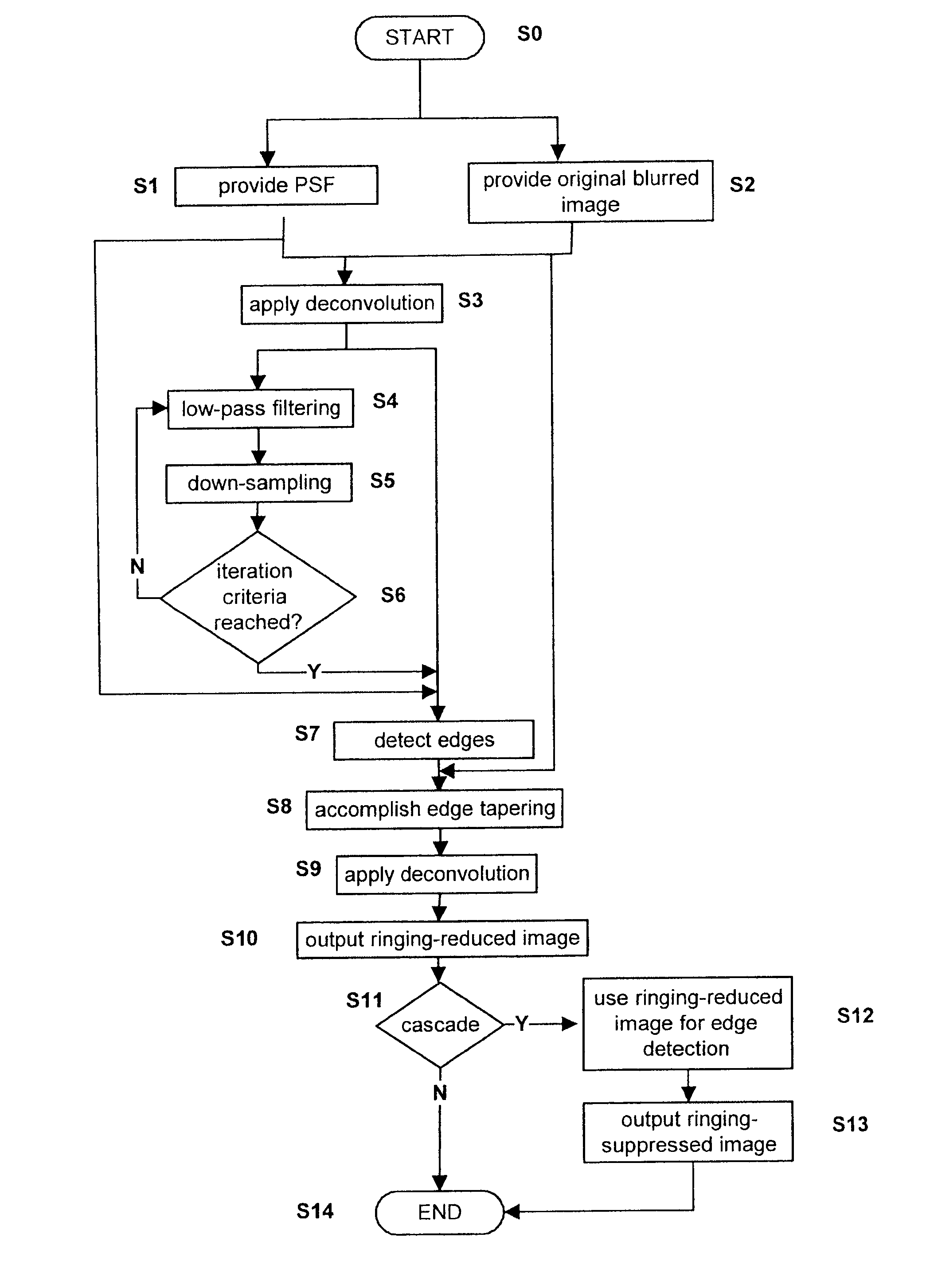
The present invention relates to a method for reducing ringing artifacts of image deconvolution. A deconvolution is applied to the original blurred image and edges are detected within the deconvolved image. Then edge tapering on the original blurred image is performed based on the detected edges.The present invention further relates to a system and a computer program product for reducing ringing artifacts of image deconvolution.

Description

FIELD OF INVENTION[0001]The present invention relates to a method for reducing ringing artifacts in image data, to a computer program product for performing the steps of the method, to a system for reducing ringing artifacts in image data and to an imaging device comprising a system for ringing artifacts reduction. Specifically, the present invention relates to ringing artifact reduction of image deconvolution.BACKGROUND OF THE INVENTION[0002]When an image is taken it can be blurred due to for example handshake or the like. If the point spread function (PSF) is known, a deconvolution method can be applied to the blurred image to restore the original image from the blurry one. However, with most image deconvolutions ringing artifacts occur as a side effect, in particular if the point spread function in the frequency domain has nulls.[0003]Different approaches have been carried out to reduce ringing artifacts of image deconvolution. One approach proposes image deconvolution using natu...

Claims


Application Information

Patent Timeline
Patent Type & Authority Patents(United States)
IPC IPC(8): G06K9/40
CPCG06T5/003G06T2207/20192
Inventor LEI, ZHICHUNZIMMERMANN, KLAUS
Owner SONY CORP
Learn More