System and method for distributed power control in a communications system

a communication system and distributed power technology, applied in the field of digital communications, can solve the problems of significantly reducing system performance, inter-link interference may have a significant impact on the overall performance of the communications system, etc., and achieve the effect of reducing the impact of existing communications systems, increasing implementation costs, and improving system performan

Inactive Publication Date: 2013-11-19
FUTUREWEI TECH INC
View PDF15 Cites 213 Cited by
  • Summary
  • Abstract
  • Description
  • Claims
  • Application Information

AI Technical Summary

Benefits of technology

[0011]One advantage disclosed herein is that multiple communications hops are considered when designing power control, thereby improving system performance (such as the sum of the data rate, also referred to as system throughput).
[0012]A further advantage of exemplary embodiments is that the power control is fully distributed and does not require a centralized controller that may increase implementation costs, as well as communications overhead and protocol latency. Thereby, the impact to existing communications systems may be minimized.

Problems solved by technology

Typically, in a multi-user communications system, inter-link interference may have a significant impact on overall performance of the communications system.
For example, inter-link interference may significantly reduce the system performance, such as a sum of the data rates of links simultaneously utilizing the same radio frequency resource.
However, they tend to be optimized for single-hop power control algorithms and do not typically apply to communications systems with relay nodes since such systems are multi-hop systems.

Method used


Image

  • System and method for distributed power control in a communications system
  • System and method for distributed power control in a communications system
  • System and method for distributed power control in a communications system

Examples


Embodiment Construction

[0022]The making and using of the current example embodiments are discussed in detail below. It should be appreciated, however, that the present invention provides many applicable inventive concepts that can be embodied in a wide variety of specific contexts. The specific embodiments discussed are merely illustrative of specific ways to make and use the invention, and do not limit the scope of the invention.

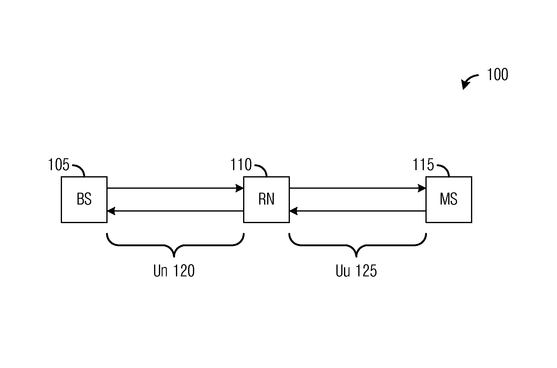
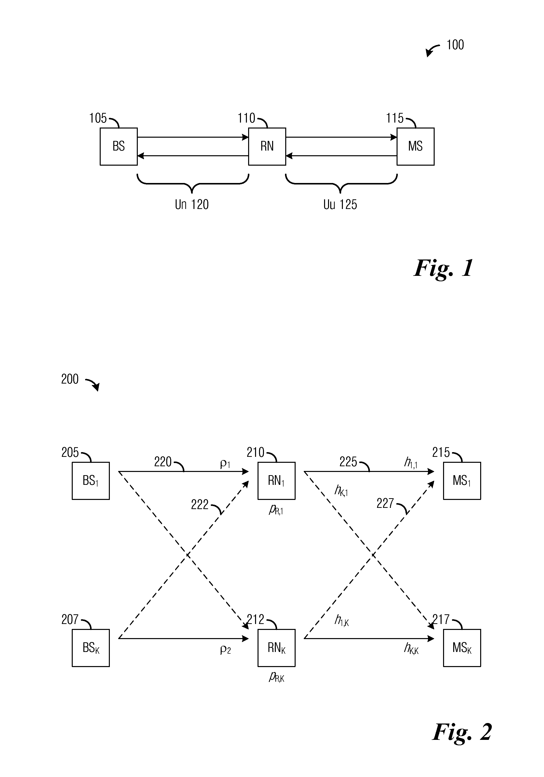
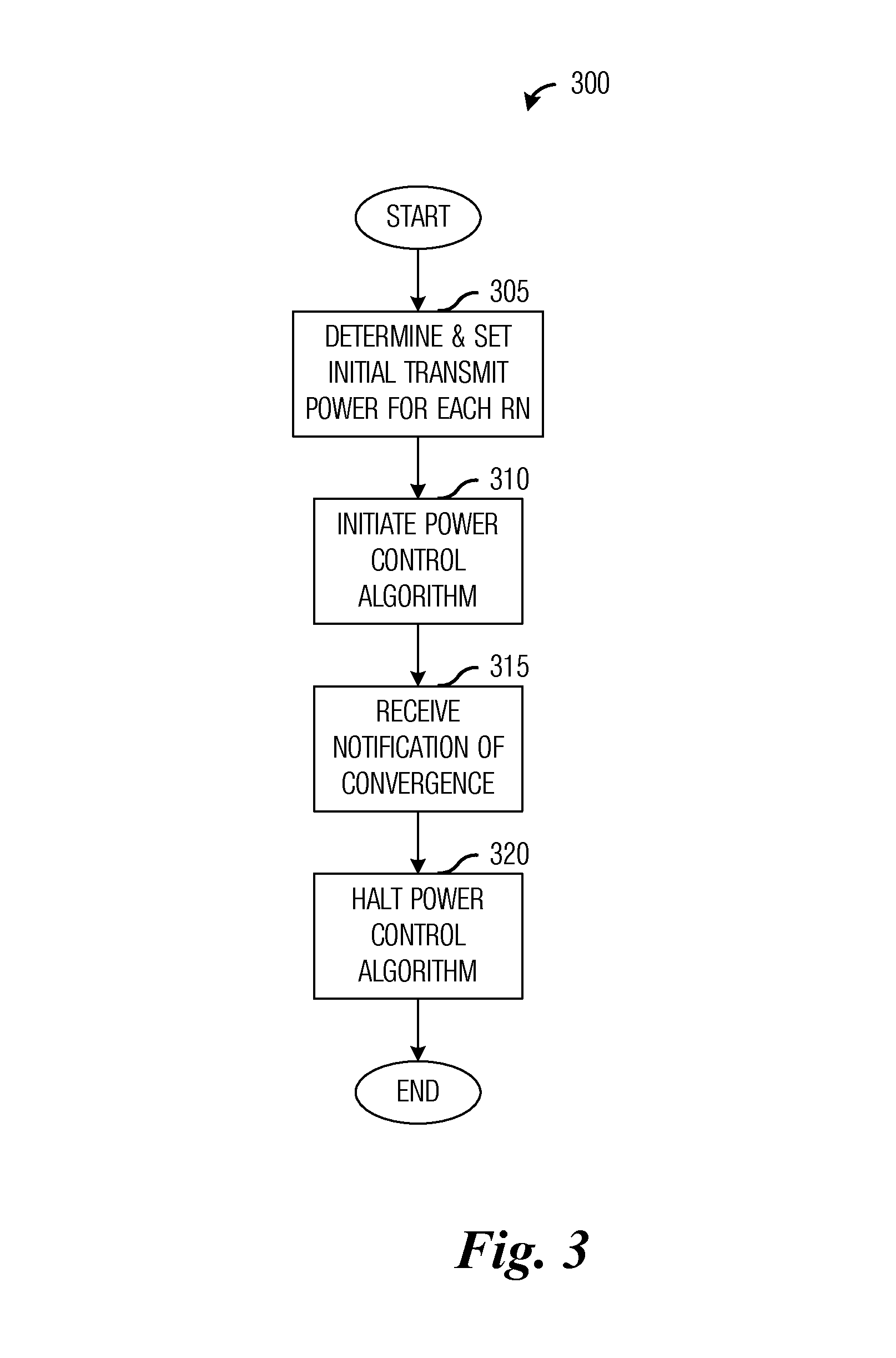
[0023]One example embodiment of the invention relates to providing power control in a multi-hop communications system. For example, after initiating channel measurements of a second hop, a relay node transmits a signal to help a mobile station perform the channel measurements. The relay node uses the information related to the channel measurements and attempts to update the power level of transmissions to the mobile stations by converging the channel quality of the second hop with a convergence value. At a base station, initial transmit power levels are set for the relay node, an...


PUM


Abstract

A system and method for distributed power control in a communications system are provided. A method for relay node operations includes transmitting a signal at a transmit power level on a first channel from a relay node to a user equipment, receiving a message comprising a first indication of channel quality of the first channel at the transmit power level, and determining a second indication of channel quality of a second channel between a communications controller and the relay node, where the first channel and the second channel are in a same multi-hop communication path. The method also includes altering the transmit power level of the first channel based on the first indication of channel quality and the second indication of channel quality to converge the channel quality of the first channel to a convergence value.

Description

[0001]This application claims the benefit of U.S. Provisional Application No. 61 / 388,339, filed on Sep. 30, 2010, entitled “Method for Distributed Power Control at the Relay Nodes in Wireless Relay Networks,” which application is hereby incorporated herein by reference.TECHNICAL FIELD[0002]The present invention relates generally to digital communications, and more particularly to a system and method for distributed power control in a communications system.BACKGROUND[0003]Relay nodes may be introduced into a communications system to extend coverage and / or to improve data rate. For example, in a downlink of a relay-based communications system, a base station (BS) (also commonly referred to as a controller, communications controller, NodeB, enhanced NodeB (eNB), and so on) may transmit to a relay node (RN), which in turn retransmits to a mobile station (MS) (also commonly referred to as a subscriber, terminal, user, User Equipment (UE), and so forth).[0004]Typically, in a multi-user co...

Claims


Application Information

Patent Timeline
Patent Type & Authority Patents(United States)
IPC IPC(8): H04B7/00H04B17/40
CPCH04W52/46
Inventor TRUONG, KIEN TRUNGKWON, YOUNG HOONSARTORI, PHILIPPE
Owner FUTUREWEI TECH INC
Why Eureka
Try Eureka