Tamper respondent covering

a respondent and tampering technology, applied in the field of tampering respondent covering, can solve the problems of preventing conventional use, requiring a large amount of time, and destroying one or more lines, etc., and preventing conventional us

Active Publication Date: 2013-11-19
LEE CHEOL JAE
View PDF4 Cites 76 Cited by
  • Summary
  • Abstract
  • Description
  • Claims
  • Application Information

AI Technical Summary

Benefits of technology

[0016]According to the present invention, when the tamper covering of the present invention is provided for an electronic device equipped with an important electronic part to be protected, a tampering operation wherein it is attempted to remove the covering from the substrate or to drill a hole in the covering is detected, and then the operation of the electronic part to be protected is disabled or data is erased. Accordingly, the covering of the present invention has the advantage of preventing the electronic device to be protected from being illegally used.

Problems solved by technology

As noted above, all attempts to penetrate the enclosure result in damaging to one or more of the lines, which is detected by the change in the electrical characteristics of the conductor.
It may however be relatively time-consuming and expensive to enclose and surround the item with such an enclosure.
Also, the provision of an enclosure which completely surrounds an item restricts the manner in which the item may be located and positioned within a larger device and is likely to, for example, preclude conventional surface mounting.
The side walls are not protected by the pattern of serpentine conductors and therefore present an area susceptible to attack, as does the system of ball grid array interconnections.

Method used


Image

  • Tamper respondent covering
  • Tamper respondent covering
  • Tamper respondent covering

Examples


first embodiment

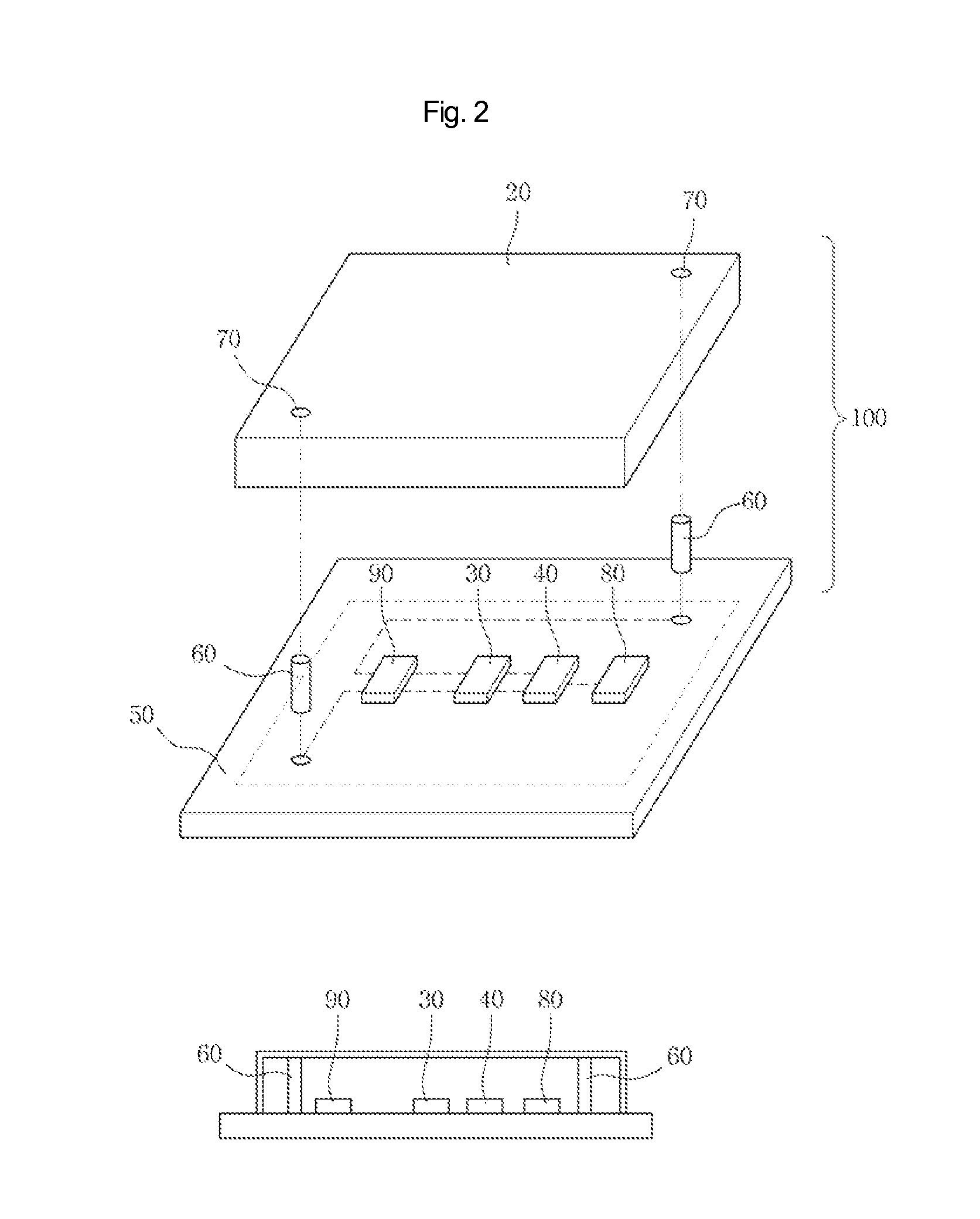
[0025]FIG. 2 is a perspective view illustrating a tamper respondent covering according to the present invention.

[0026]A temper respondent covering 100 includes a cover 20, devices 30 and 40 mounted on a Printed Circuit Board (PCB), a connector 60 made of a conductive rubber or a metal, a contact connected to the connector 60, and a controller 80. The covering 100 further includes a power supply unit 90 to supply power because the covering 100 is a portable part. The power supply unit 90 may be provided as a battery. The battery may be, but is not limited to, a lithium battery or a lithium ion battery. Any type of battery can be used as long as these have the same or equivalent function as the exemplary batteries.

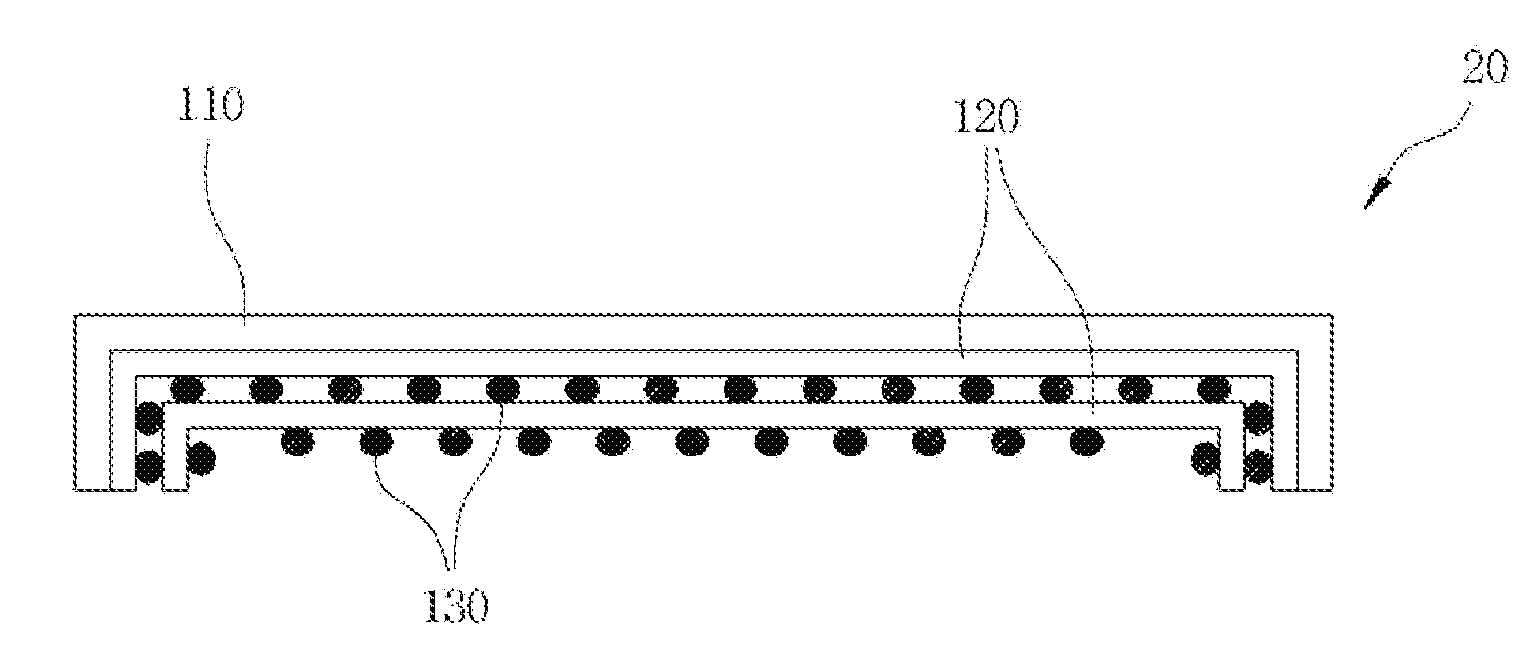
[0027]The device 30 detects a tampering operation, and the device 40 is a storage device in which data concerning security or certification is stored. When an external shock is applied to the covering, for example, when someone attempts to remove the substrate 50 from the co...


PUM


Abstract

Disclosed is a tamper respondent covering. The tamper respondent covering has a cover-shaped structure to cover an electronic part which is exposed. This covering protects electronic parts embedded inside or exposed outside a product, such as ICs that contains data concerning security and certification, communication connectors that transmit data, etc. from a tempering operation or an alternating operation. The tamper respondent covering protects data from a tampering operation or an altering operation by erasing the data or disabling operation of the electronic part containing the data in response to an act of attempting to remove the covering from a printed circuit board of the electronic part or to drill a hole in the covering.

Description

CROSS REFERENCE TO RELATED APPLICATIONS[0001]Pursuant to 35 U.S.C. §119(a), this application claims the benefit of earlier filing date and right of priority to Korean Patent Application No. 10-2012-0042664 filed on Apr. 24, 2012, the contents of which are hereby incorporated by reference herein in their entirety.BACKGROUND OF THE INVENTION[0002]1. Field of the Invention[0003]The present invention relates to a tamper respondent covering, and, more particularly to a tamper respondent covering that protects data from a tampering operation by covering electronic parts such as, integrated circuits (ICs) that are embedded inside or exposed outside a product and contain data concerning security and certifications, and communication connectors that transmit data, etc. using a cover-shaped structure and by erasing important data stored in the electronic part to be protected or disabling the operation of the electronic part when it detects tampering of the electronic part to be protected, for...

Claims


Application Information

Patent Timeline
Patent Type & Authority Patents(United States)
IPC IPC(8): G06F21/00
CPCG06F21/86G06F2221/034G06F2221/2101H05K5/03
Inventor LEE, CHEOL JAE
Owner LEE CHEOL JAE
Why Eureka
Try Eureka