Shaver

a shaver and handle technology, applied in the field of shavers, can solve the problems of force supporting the cartridge body, undesired removal of the cartridge body, and undesired removal of the cartridge body, and achieve the effect of simplifying the structur

Active Publication Date: 2013-11-26
DORCO CO LTD
View PDF42 Cites 117 Cited by
  • Summary
  • Abstract
  • Description
  • Claims
  • Application Information

AI Technical Summary

Benefits of technology

[0016]Accordingly, the present invention has been made keeping in mind the above problems occurring in the prior art, and an object of the present invention is to provide a shaver, which simplifies the structure by which a cartridge is removably coupled to a handle assembly.
[0017]Another object of the present invention is to provide a shaver, which increases the force with which a cartridge is coupled with a handle assembly to resist external force.
[0018]A further object of the present invention is to provide a shaver, which has increased cartridge supporting force, and has an improved structure for rotating a cartridge.Technical Solution

Problems solved by technology

However, the conventional shaver constructed as described above has the following problems.
The shaver is problematic in that the pivot support structure for rotating the cartridge body 1a is weak, so that the cartridge 1 may be undesirably separated from the handle 2 or may break when external force is applied to the cartridge 1 during the operation of coupling or removing the cartridge 1 to or from the handle 2 or during shaving.
Thus, when external force is applied to the cartridge 1 during the operation of coupling or removing the cartridge 1 to or from the handle 2 or during shaving, the pivot support shafts 1e may be undesirably removed from the cartridge body 1a, or may break.
Further, the shaver is problematic in that ends of the pivot support shafts 1e which are to be coupled to the cartridge body 1a are inserted into holes formed in the cartridge body 1a to support the cartridge body 1a, so that the force supporting the cartridge body 1a is weak.
Further, the shaver is problematic in that the coupling part 2b of the handle 2 is removably coupled to the housing 1f of the cartridge 1 using the elastic force of a spring, so that the removable structure is complex, and undesirable removal may occur when external force is applied.

Method used


Image

  • Shaver
  • Shaver
  • Shaver

Examples


Embodiment Construction

[0047]Hereinafter, the preferred embodiment of the present invention, which accomplishes the above objects, will be described with reference to the accompanying drawings.

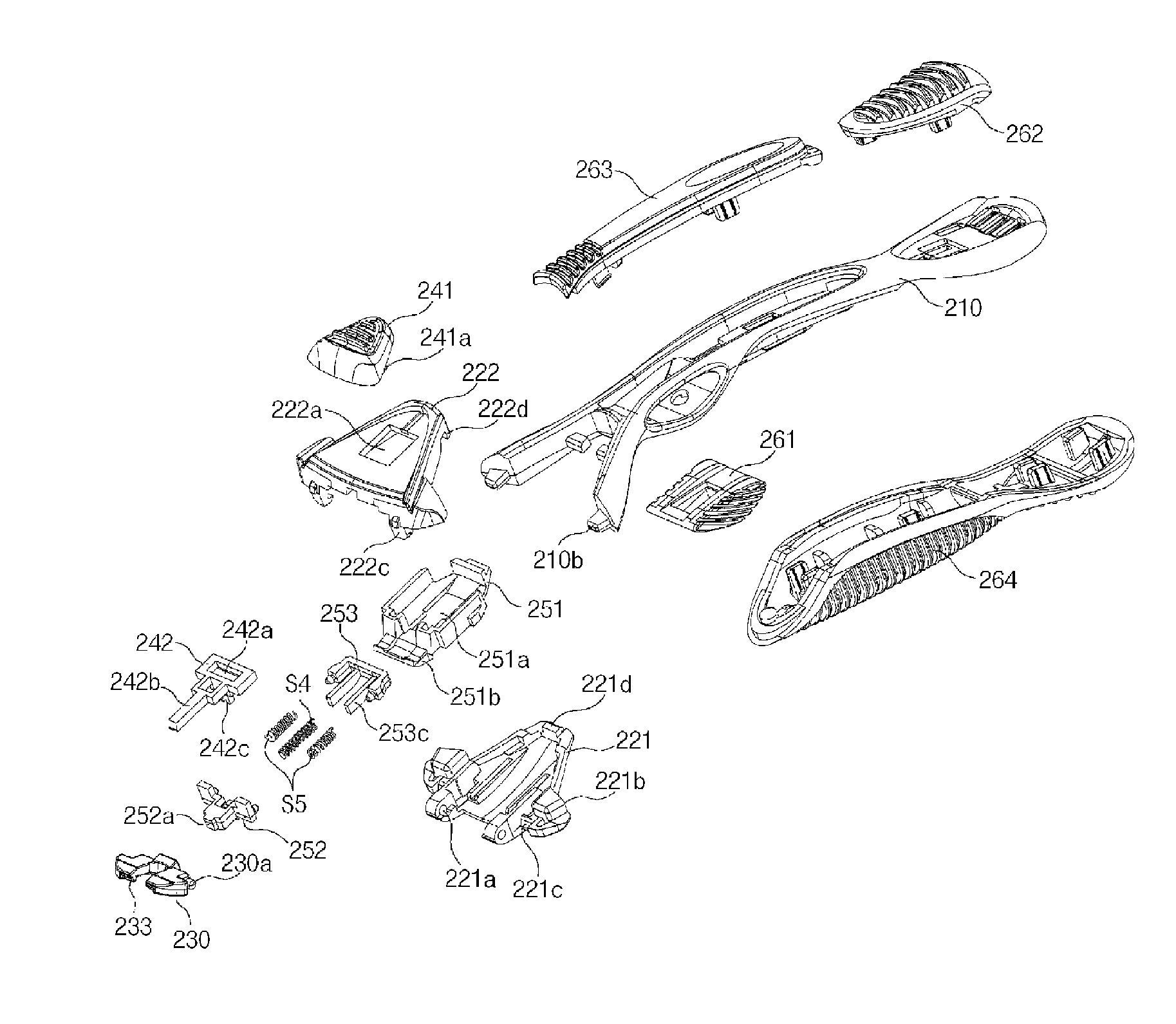
[0048]FIG. 5 is a plan view showing a shaver, according to the preferred embodiment of the present invention, FIG. 6 is a bottom view showing the shaver, according to the preferred embodiment of the present invention, FIG. 7 is a perspective view showing the state in which a cartridge and a handle assembly included in the shaver of FIG. 5 are separated from each other, FIG. 8 is an exploded perspective view showing the handle assembly of FIG. 5, and FIG. 9 is an exploded perspective view showing important parts of FIG. 8.

[0049]Further, FIG. 10 is a bottom exploded perspective view showing the cartridge of FIG. 5, FIG. 11 is a bottom view showing the cartridge of FIG. 5, FIG. 12 is a sectional view taken along line A-A of FIG. 11, FIG. 13 is a plan view showing the state in which a holder of FIG. 8 is connected to a ...


PUM


Abstract

Disclosed herein is a shaver. The shaver includes a removable cartridge and a handle assembly. The removable cartridge includes a cartridge body, at least one blade mounted to the lower surface of the cartridge body, a connector mounting part provided on the upper surface of the cartridge body, and a connector mounted to the connector mounting part and having a holder mounting part. The handle assembly includes a handle body, a housing provided on a front end of the handle body, a holder mounted to a front end of the housing in such a way as to rotate around a pivot shaft, a removing means functioning to removably couple the holder to the holder mounting part, a manipulating means installed in the housing to be operated in conjunction with the removing means, and a support means elastically supporting rotating motion of the holder using elastic force.

Description

RELATED APPLICATIONS[0001]This application is a 371 application of International Application No. PCT / KR2008 / 003039, filed May 30, 2008, which in turn claims priority from Korean Patent Application No. 10-2007-0053545, filed May 31, 2007, both of which are incorporated herein by reference in their entirety.TECHNICAL FIELD[0002]The present invention relates, in general, to shavers and, more particularly, to a shaver, which improves the structure of a cartridge and a handle assembly, thus simplifying the structure by which the cartridge is removably coupled to the handle assembly, and which allows the cartridge to smoothly rotate during shaving, thus increasing shaving efficiency, and which is constructed so that the cartridge is not easily separated from the handle assembly even if external force is applied to the cartridge, thus increasing the reliability of a product.BACKGROUND ART[0003]Hereinafter, a conventional shaver will be described in detail with reference to the accompanying...

Claims


Application Information

Patent Timeline
Patent Type & Authority Patents(United States)
IPC IPC(8): B26B21/00B26B21/52
CPCB26B21/225B26B21/08B26B21/40
Inventor PARK, YOUNG HOAN, BYUNG SUN
Owner DORCO CO LTD
Why Eureka
Try Eureka